A robot arm has to answer one question, over and over: where is my gripper right now?
That sounds easy. It is not, and the way robots answer it is the foundation for almost everything else they do. This area works up to the answer over five small programs you can read and run.
This doc is for a beginner who has read the two chapters before it: Python and NumPy, then angles, vectors and matrices. Steps 1 to 3 are plain Python. Steps 4 and 5 hand the arm to ROS (Robot Operating System), which is taught later, in the ROS and RViz book. On a first read, stop after step 3 and come back to steps 4 and 5 once you have met ROS. Nothing in the next chapters needs them.
The arm used in this doc#
Everything below is explained on one example arm. It is worth fixing in your head before going on:
- 2 joints, numbered from the base outwards, called
q1andq2 - 2 rigid links, called
L1andL2 - a gripper, bolted to the far end of link 2 — it is not a joint
The arm is flat, as if lying on a table. That keeps it to one angle instead of three, and none of the ideas change.
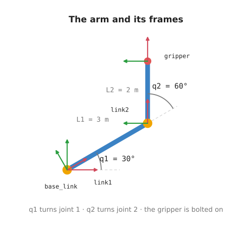
| Name | What it is | Value |
|---|---|---|
q1 | angle of joint 1, the one attached to the base | changes |
q2 | angle of joint 2, at the far end of link 1 | changes |
L1 | length of link 1 | 3 m, fixed |
L2 | length of link 2 | 2 m, fixed |
q1 and q2 are the two things the robot controls. L1 and L2 were decided
when the arm was built. The gripper never moves relative to link 2, because it
is bolted to it.
The lengths are 3 m and 2 m, and the worked examples use 30°, 45° and 60°. Right angles would give whole numbers everywhere, but they also lay a link flat along an axis and flatten the very angle each picture is trying to show. Slanted angles keep the drawings readable.
One number pays for that: 3 · cos(30°) is 2.598..., and it cannot be tidier,
because cos(30°) is sqrt(3)/2. The pose below keeps it to that one value,
which then turns up again and again, while everything else lands on a half.
We build up to this arm rather than starting there. Section 2 uses a simpler one first: a single joint with a single link.
Contents#
- The question this area answers
- Start simple: one joint, one link
- Step 1: two joints, worked out by hand
- Step 2: describe each part once · What a frame is · What a transform is · Turning a point · Applying a transform: turn, then shift · Joining two transforms · Why describe each part once
- Step 3: backwards, and carrying a point · Flipping a transform · Carrying a point
- Step 4: hand the arm to ROS
- Step 5: ask instead of working it out
- Making the arm bigger
- All the maths on one page
- Running it
- Notes
1. The question this area answers#
Say the gripper is at (0.43, 0.65).
Those two numbers are useless on their own. Measured from where? From the table the arm is bolted to? From joint 2? From the far end of link 1? Each gives a different pair of numbers for the same gripper in the same place.
So a position always comes with a starting point. Robots have a lot of them: the table has one, each joint has one, and the gripper has one.
The work is nearly always moving between those starting points:
- The gripper holds a tool. Where is the tip of it?
- A part is sitting at a known spot on the table. Where is it, measured from the gripper?
- You want the gripper at a spot on the table. What should each joint do?
These look like three problems. They are one problem, asked three ways. This area builds the piece of maths that answers all three, then hands it to ROS.
2. Start simple: one joint, one link#
Before the two-joint arm, take the smallest arm there is. One joint, one link, the gripper bolted straight onto the end:
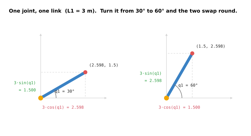
The link leaves the base at angle q1 and is L1 long. So where is the
gripper?
gripper_x = L1 · cos(q1)
gripper_y = L1 · sin(q1)
That is all cos and sin do here. They turn "this far away, at this angle"
into "this far across, this far up". Nothing more.
The picture above shows both of those as the two sides of a right-angled
triangle: L1·cos(q1) across the bottom, L1·sin(q1) up the side.
Try q1 = 30°. cos(30°) is 0.866... and sin(30°) is exactly 0.5, so the
gripper is at (3 · 0.866..., 3 · 0.5), which is (2.598, 1.5).
Now turn the same link to 60°, in the right-hand picture. The answer is
(1.5, 2.598) — the same two numbers, swapped. That is cos and sin trading
places: what one gives at 30°, the other gives at 60°.
Step 1 prints a table of these before it does anything else.
One joint is easy. The interesting part starts when there are two.
3. Step 1: two joints, worked out by hand#
File: step1_positions.py. Plain Python, no ROS.
Now add joint 2 and link 2. Joint 2 sits at the far end of link 1, which is exactly where the one-joint arm's gripper was:
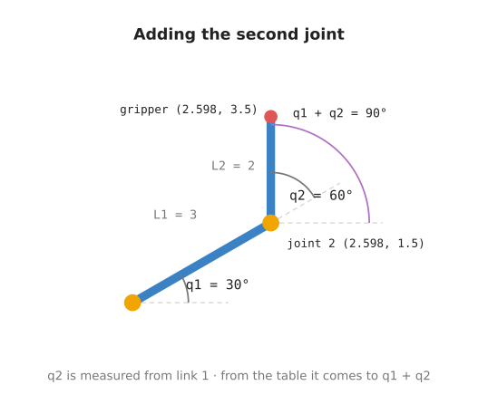
So the first half is already done. With q1 = 30°, joint 2 is at
(2.598, 1.5), same as the one-joint arm's gripper.
The catch is the angle of link 2, and the picture shows it. There are two arcs
at joint 2. The grey one is q2, measured from link 1. The purple one is the
angle from the table, and it is the bigger of the two.
q2 is measured against link 1, not against the table. Link 1 is already turned by q1. So measured from the table, link 2
points at q1 + q2:
gripper_x = joint2_x + L2 · cos(q1 + q2)
gripper_y = joint2_y + L2 · sin(q1 + q2)
The picture uses q2 = 60°. Link 1 is already turned by 30°, so from the table
link 2 points at 30° + 60° = 90° — straight up. The gripper is therefore L2
above joint 2: (2.598, 1.5 + 2), or (2.598, 3.5).
Look at the picture again. There are two arcs at joint 2, and they are different
sizes. The small one is q2 = 60°, measured from link 1. The large one is
q1 + q2 = 90°, measured from the table. That gap is the whole point of this
section.
Try it with both joints straight instead, q1 = 0 and q2 = 0. Every cosine is
1 and every sine is 0, so the gripper is at L1 + L2 = 5 metres straight out. A
straight arm at full stretch. That is right, and step 1 prints exactly that.
This works. So why not stop here?
Because those two formulas were worked out by hand, for this arm, to answer this one question. Change anything and you do it again:
- add a third joint, and you rewrite them
- move to 3D, and every step needs three angles instead of one
- ask a different question — "where is the table, from the gripper's point of view?" — and you work out a fresh set backwards
Step 2 gets the same numbers without working out anything.
4. Step 2: describe each part once#
File: step2_frames.py. Still plain Python.
Step 1 worked. But the formula it used answered one question, about one arm, and you had to work it out yourself.
Here we do the opposite. We never describe the whole arm. We describe each piece on its own, in the simplest terms we can, and then let the pieces be combined.
That sounds like more work. It is less, and this section is mostly about why.
What a frame is#
A frame is a starting point with axes, stuck to one physical thing. When that thing moves, its frame moves with it.
Why bother? Because a pair of numbers on its own says nothing.
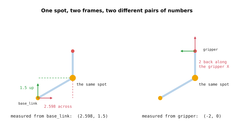
Both panels show the same spot: joint 2. Nothing moved between the two pictures. The numbers are completely different, because they are measured from different places.
- From
base_link, joint 2 is at (2.598, 1.5). Awkward numbers, and they change every time the arm moves. - From
gripper, the same spot is at (-2, 0). That means two metres straight back along the gripper's own X axis — and it never changes, because link 2 is rigid.
Same spot, two frames, two answers, and neither is more correct than the other. That is the whole reason frames exist: each part of a robot has its own natural way to describe where things are, and it is usually the simple one.
This arm has four frames:
flowchart LR
    base_link -->|"turn by q1"| link1
    link1 -->|"move L1, turn by q2"| link2
    link2 -->|"move L2"| gripper
| Frame | Stuck to |
|---|---|
base_link | the table the arm is bolted to |
link1 | link 1, so it turns with joint 1 |
link2 | link 2, so it turns with joint 2 |
gripper | the gripper, at the far end of link 2 |
Every frame has exactly one parent, the part it is attached to. That is what lets them be joined up in order.
What a transform is#
A transform says where a child frame sits inside its parent. Three numbers say it completely: how far across, how far up, and how much turned.
Those three numbers are really just two moves:
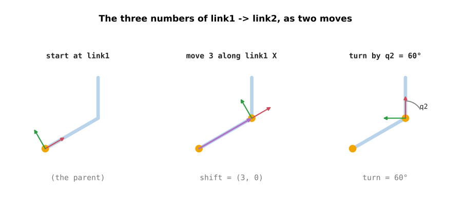
Read it left to right. Start at link 1's frame. Move 3 metres along link 1's own
X axis, which lands you at joint 2. Then turn 60°. You are now sitting in link
2's frame. Shift (3, 0), turn 60° — that is the whole transform.
The arm needs three of them, and each one is short:
| From | To | The transform | Changes? |
|---|---|---|---|
base_link | link1 | turn by q1, no shift | yes, joint 1 |
link1 | link2 | shift L1 across, turn by q2 | yes, joint 2 |
link2 | gripper | shift L2 across, no turn | no, bolted on |
Read the second row as a sentence: link 2 starts 3 m along link 1, turned by
q2 from it.
Now look at what that sentence does not mention. Not the table. Not joint 1. Not the gripper. It is a fact about joint 2 and nothing else, so whoever built that joint could have written it down without knowing what the rest of the robot looks like.
The last row never changes at all. It was measured once, when the arm was built. TF does not treat it differently from the joints — a transform is a transform.
Turning a point#
To combine transforms we need one formula: turning a point about the origin.
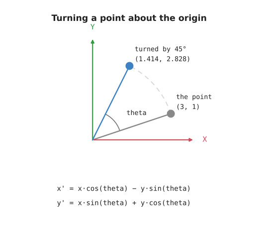
A point sits some distance out, at some angle. Turning it by t leaves the
distance alone and adds t to the angle. Writing that out in x and y gives:
x' = x · cos(t) - y · sin(t)
y' = x · sin(t) + y · cos(t)
Check it on a point you can picture. Take (1, 0), which is one metre along X,
and turn it a quarter turn, so t = 90°. Then cos(90°) = 0 and
sin(90°) = 1:
x' = 1 · 0 - 0 · 1 = 0
y' = 1 · 1 + 0 · 0 = 1
The answer is (0, 1): one metre along Y. The point that pointed along X now
points along Y, which is what a quarter turn should do.
The picture turns (3, 1) by 45°, which lands on (1.414, 2.828). Less tidy
than the check above, but it is the general case: both terms of each formula do
some work, rather than one of them vanishing.
This is rotate_point() in arm_math.py, and it is the only formula in the
area. Everything below is built from it.
Applying a transform: turn, then shift#
A transform is used to move a point from the child frame out into the parent. That takes two steps, and they go in this order:
- turn the point by the transform's angle
- then add the transform's shift
The order is not a matter of taste. Doing it the other way gives a different answer:
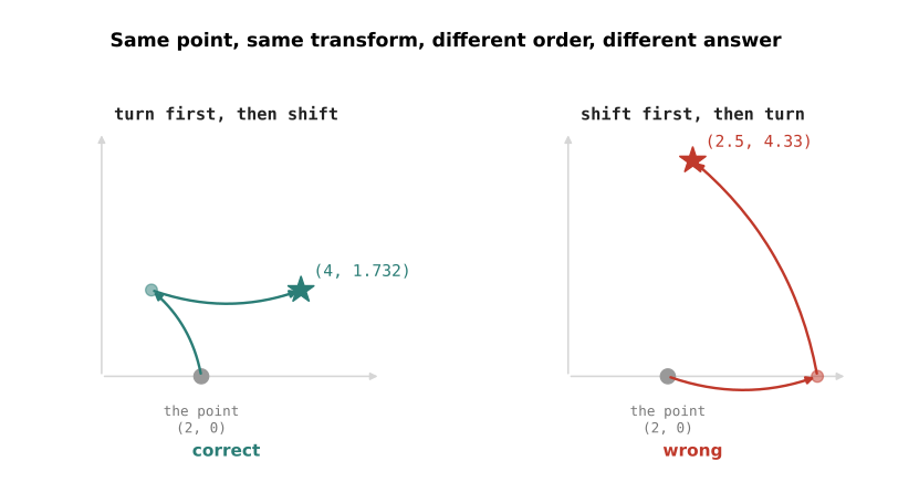
Both panels start with the same point, (2, 0), and use the same transform:
shift (3, 0), turn 60°.
- Turn first, then shift: the point lands at (4, 1.732).
- Shift first, then turn: it lands at (2.5, 4.33).
Why so different? Shifting first pushes the point away from the origin. The turn then swings that shift around as well, which was never meant to happen. The shift was measured along the parent's axes. It has to be added after all the turning is done.
This is Transform2D.apply().
Joining two transforms#
Now the useful part. Two transforms end to end can be replaced by one.
Take the first two rows of the table above, with q1 = 30° and q2 = 60°:
base_link→link1is: shift(0, 0), turn30°link1→link2is: shift(3, 0), turn60°
To get base_link → link2 directly, there are two rules.
The angles add. 30° + 60° = 90°.
The second shift has to be turned first. The (3, 0) was measured along
link 1, and link 1 is turned by 30°. So turn (3, 0) by 30° before using it:
x = 3 · cos(30°) - 0 · sin(30°) = 3 · 0.866... = 2.598
y = 3 · sin(30°) + 0 · cos(30°) = 3 · 0.5     = 1.5
That is the same rule as the section above, and for the same reason. The second transform's shift is written in the first one's tilted axes. So it has to be turned before it can be added.
Then add the first shift, which here is (0, 0). So base_link → link2 is a
shift of (2.598, 1.5) and a turn of 90°.
That (2.598, 1.5) should look familiar. It is where joint 2 was in section 3,
and where the one-joint arm's gripper was in section 2. Same point, reached three
different ways.
Join the third row on the same way — shift (2, 0), no turn. This time the shift
gets turned by the running 90°, so (2, 0) becomes (0, 2), and adding it gives
base_link → gripper: a shift of (2.598, 3.5) and a turn of 90°.
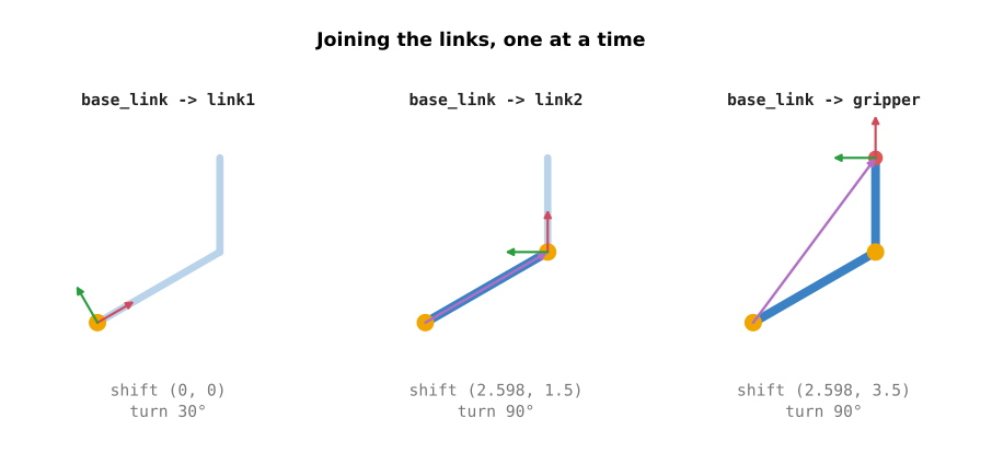
Each panel adds one link. The frame walks out along the arm, and the shift and turn underneath it are the answer so far. Step 2 prints exactly these three lines, so you can watch it happen.
This is Transform2D.then().
Why describe each part once#
Here is the payoff, and it is easiest to see by moving a joint.
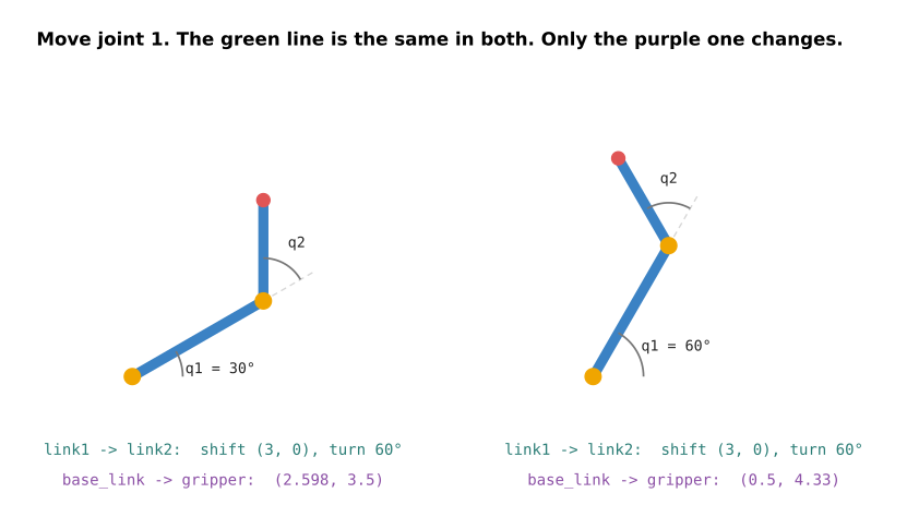
Both panels show the same arm, with joint 1 turned to a different angle.
The green line is identical in both. link1 → link2 is still shift
(3, 0), turn 60°. Moving joint 1 did not make that fact stale, because it
never depended on joint 1 in the first place.
The purple line is different in each. base_link → gripper had to change,
because the gripper really did move.
So the things you write down by hand are the green ones. They are short, local, and stay true whatever the rest of the robot does. The purple one — the answer you actually wanted — is never written down. It is worked out by joining, fresh, each time somebody asks.
That is what "describe each part once" buys you: nothing to keep in sync.
It also explains where the added angles came from. Step 2 finishes by checking itself against step 1, and prints the difference. The difference is zero, at every pose.
Look back at section 3, where we had to notice that link 2 points at q1 + q2
and write it in ourselves. Nothing in step 2 mentions q1 + q2. Each transform
only knows its own joint. The q1 + q2 appeared anyway, because joining adds the
angles.
A third joint would produce q1 + q2 + q3 on its own, with no new thinking and
no new formulas.
5. Step 3: backwards, and carrying a point#
File: step3_chain.py. Still plain Python.
Two more moves, and both were awkward in step 1.
Flipping a transform#
If you know where the gripper is on the table, you already know where the table is from the gripper's point of view. You do not measure anything new. You undo the turn, and undo the shift:
flipped angle = -angle
flipped shift = turn the shift by -angle, then flip its sign
At the pose we have been using, base_link → gripper is a shift of
(2.598, 3.5) and a turn of 90°.
Flipped, gripper → base_link is a shift of (-3.5, 2.598) and a turn of
-90°. Step 3 prints both, one under the other.
Look at what happened to the shift. (2.598, 3.5) did not simply change sign.
The same two numbers came back swapped, with one negated, because the shift
had to be turned by -90° on the way out.
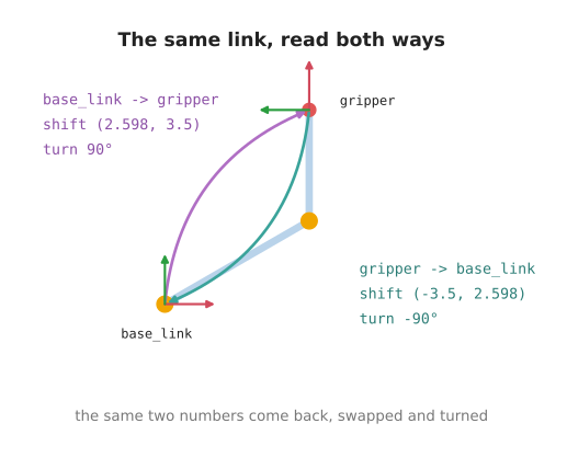
Same two frames, same arm, no new measurement. Only the direction of the question changed, and the numbers are completely different because they are now measured along the gripper's axes instead of the table's.
This is how a robot answers "where is the table, from the gripper?" when all anyone told it is how far each joint has turned.
A good check: flip it twice and you must get back exactly what you started with. The tests do that at several poses.
This is Transform2D.inverse().
Carrying a point#
A gripper holding a tool cares about the tip, not the gripper itself.
The tip is easy to describe in the gripper frame: 1 m straight ahead. And it
stays (1, 0) there forever, no matter how the arm moves, because it is bolted
to the gripper.
To find the tip on the table, apply base_link → gripper to that fixed point:
turn it, then add the shift. At the pose we have been using the tip lands at
(2.598, 4.5). At the second pose in the picture, q1 = 60° and q2 = -60°,
it lands at (4.5, 2.598) — the same two numbers again, the other way round.
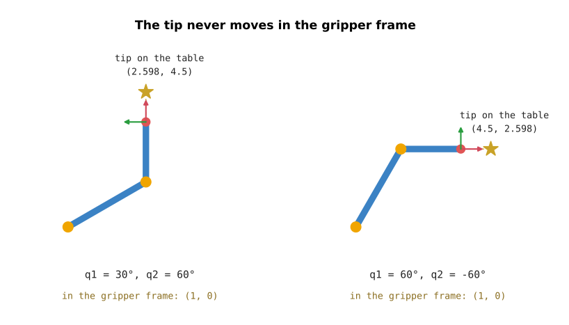
Two poses, one point. The bottom line is (1, 0) in both, because that is the
tip's description in the gripper frame and it never changes. The number by the
star is different in each, because that is the table's answer.
Move the arm and run step 3 again. The description in the gripper frame does
not change. The answer on the table does. This is the same idea as the ball in
the RViz area: you do not move the thing, you move the
frame it is attached to.
This is Transform2D.apply().
6. Step 4: hand the arm to ROS#
This step and the next one need ROS. If you have not read the ROS and RViz book yet, skip to section 8.
File: step4_broadcast.py. This is the first one that uses ROS.
So far everything has been one program talking to itself. Nothing else on the robot could ask where the gripper was.
TF fixes that. It is the part of ROS that keeps track of frames, and the name is just short for transform. Programs publish the transforms they know about, and TF joins them up for anyone who asks.
Step 4 publishes the arm's three transforms, thirty times a second, as the joints swing:
base_link -> link1      turn by q1              (joint 1)
link1     -> link2      move L1, turn by q2     (joint 2)
link2     -> gripper    move L2                 (bolted on)
The maths did not change at all. Step 4 imports the same list of transforms step 2 used, and only turns each one into a ROS message before sending it.
Two things are worth noticing.
Each link is published on its own. Step 4 never publishes base_link →
gripper, even though it could work it out easily. Each program publishes only
what it actually knows.
The shapes are drawn in their own frames. The bar for link 1 is described
inside link1, and it never moves there. TF moves the frame, and the bar goes
along with it. Five shapes, none of which are ever repositioned.
7. Step 5: ask instead of working it out#
File: step5_lookup.py. This is where it pays off.
Nobody published base_link → gripper. This program asks for it anyway:
buffer.lookup_transform('base_link', 'gripper', Time())
TF joins the three published links and answers.
Now open the file and look for trigonometry. There is none. No cos, no sin,
no q1 + q2. It never imports arm_math. It does not know how long the links
are, how many joints there are, or that the arm is flat.
It only knows two frame names.
That is the reason for all the work in steps 2 and 3. Describe each part once, in the one place that knows it. Publish that. Then any other program can ask about any pair of frames, without knowing how the robot is built.
8. Making the arm bigger#
Everything above was shown on two joints. Here is what actually changes when the arm grows.
A third joint and a third link. Add one row to the list of transforms:
link2 -> link3     move L2, turn by q3
link3 -> gripper   move L3
Nothing else changes. Joining still adds the angles, so q1 + q2 + q3 appears
on its own. Step 5 does not change at all — it still asks for two frame names.
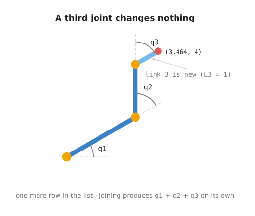
The picture adds a third link 1 m long, turned by q3 = -60°. From the table it
points at 30° + 60° - 60° = 30°, and the tip lands at (3.464, 4). No new
formula was needed to work that out.
A gripper that can turn. Right now the gripper is bolted on, so its row
never changes. Give it a joint and that row starts changing with q3 like any
other. Nothing else cares: TF treats a moving transform and a fixed one exactly
the same.
Moving to 3D. A position becomes three numbers, and a rotation needs three angles instead of one. Each of the four operations gets more arithmetic inside it, but there are still only four of them. This is the point where real code stops writing the formulas out and calls a matrix library instead.
The pattern holds at every size: describe each part once, against its immediate parent, and let the joining do the rest.
9. All the maths on one page#
Four operations. Everything above is one of them.
to turn a point by an angle:
    x' = x·cos(angle) - y·sin(angle)
    y' = x·sin(angle) + y·cos(angle)

to apply a transform T to a point:
    turn the point by T's angle
    then add T's shift

to join transform A with transform B:
    angle = A's angle + B's angle
    shift = apply A to B's shift

to flip transform A:
    angle = -A's angle
    shift = turn A's shift by -A's angle, then flip its sign
And the arm's answer, built from them:
to find the gripper on the table:
    answer = no shift, no turn
    for each transform from base_link to gripper:
        answer = join(answer, that transform)
    return answer
10. Running it#
make arm.learn     steps 1 to 3: the maths, printed, then it exits
make arm.demo      step 4: publish the arm and draw it in RViz
make arm.watch     step 5: ask TF where the gripper is (needs arm.demo running)
make arm.learn runs the three plain-Python steps back to back. Step 1 prints
the one-joint table, then the two-joint one. Step 2 prints the link-by-link
build-up, and its check against step 1. Step 3 flips a transform, and carries
the tool tip onto the table. Every number in that output is whole.
make arm.demo opens RViz with the arm swinging. The two joints move at
different speeds, so it keeps finding new poses instead of repeating a short
loop. You should see:
- two blue bars, one per link
- a yellow ball at each joint
- a red ball at the gripper
- frame arrows moving along with all of them
make arm.watch prints one line a second:
gripper at (+4.037, +2.713) facing +17.4° tool tip at (+4.991, +3.012)
The arm is swinging through every angle, so these are whatever the moment gives.
But the gap between the two pairs is always 1 m, whatever the arm does. That point never moved. It is fixed in the
gripper frame, and only the frame went anywhere.
11. Notes#
ROS stores a rotation as four numbers, called a quaternion, rather than as
angles. Three angles have an awkward case in 3D: at certain poses two axes line
up and one direction of movement quietly disappears. Four numbers have no such
case. yaw_to_quaternion() does the conversion for you, and you can use it
without following the theory.
The RViz area, in the ROS and RViz book, covers markers and the 3D viewer that steps 4 and 5 draw the arm in.
Next chapter: forward kinematics, which uses these transforms to turn a list of joint angles into a gripper position, and then asks the harder question backwards.
This area is about describing where things are. Getting the arm to a place, and what stops it, is arm movement: reach envelopes, singularities, planning a path, and controlling the move. It assumes the frames and transforms built here. The transforms are put to work again in cameras, which moves a point measured by a camera into the room the arm moves in.