Before any question about how to move, there is a question about whether the move exists. This document is about that question, and about the fact that it has four separate answers rather than one.
It is the most under-documented subject in this area. Motion planning has books, tutorials and a healthy open-source ecosystem. Reachability has a parameter in a configuration file and a solver that returns nothing when it fails. A great deal of real project time is lost here, and almost all of it is lost to failures that do not announce themselves: a pose that is reachable in one wrist configuration and not the other, a straight line whose two ends are fine and whose middle is not, a joint limit that a description file quietly narrowed, and a solver that said no when it meant "not yet".
This is written for someone who is about to bolt an arm to a table, or has done so and is now finding that a third of the poses they wanted do not work. It follows on from the overview and assumes the frames and transforms of the arm area.
Contents#
- Four things "reachable" can mean
- The workspace and its holes
- Singularities, and what the controller does at one
- Joint limits, and the range that is not there
- Configurations: the eight ways to reach the same pose
- Redundancy, and the seventh joint
- Where to bolt the arm down
- Finding out before you commit
- Cheap tests before expensive ones
- The five failures that do not announce themselves
1. Four things "reachable" can mean#
When somebody says a pose is reachable they may mean any of four different things, and a system can pass three of them and fail the fourth.
The position is inside the workspace. The tool centre point can be put at that point in space by some combination of joint angles. This is the weakest of the four and it is the one people usually check.
The position and the orientation are both achievable. Most positions inside the workspace can only be reached with the tool pointing in some directions and not others. The set of positions reachable with every orientation is called the dexterous workspace and it is much smaller than the reachable workspace — for a typical six-joint arm it is a modest region in the middle, not the whole envelope.
A joint solution exists that is also collision-free and inside the joint limits. Inverse kinematics can return an answer that puts the elbow through the table. Reachability without a collision check is a statement about geometry, not about the cell.
A path exists from where the arm is now to that solution. This is the one that is almost never checked and the one that bites. Two configurations can both be valid while no continuous motion connects them, because getting from one to the other would mean passing through a joint limit or through the table.
The table below is those four against what tells you the answer. Read it as a checklist in order: each row assumes the row above it passed.
| The question | What answers it | What it misses |
|---|---|---|
| is the point inside the envelope | arithmetic on the link lengths | orientation, entirely |
| is this full pose achievable | an inverse kinematics solver | collisions, and the joint limits if the solver ignores them |
| is there a valid, collision-free joint solution | the solver plus a planning scene | that reaching it may require passing through something |
| can the arm get there from here | a motion planner, run for real | nothing — but it is the most expensive of the four |
2. The workspace and its holes#
The reachable workspace is the set of points the tool can be put at. For an arm
whose links are L1 and L2 and whose joints have no limits, it is the region
between two spheres: an outer one at L1 + L2 and an inner one at |L1 − L2|.
The inner sphere is a hole, and nothing inside it is reachable at any joint
angle, because the two links cannot fold closer together than the difference in
their lengths.
The arm area builds an arm with L1 = 3 m and
L2 = 2 m, so its reachable region runs from 1 m to 5 m from the base. The
picture below is that region, with a move whose two ends are comfortably inside
it and whose middle is not.
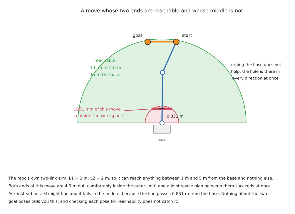
Both ends of that move sit 4.9 m from the base. Ask for a path in joint space and one is found immediately: the joints simply rotate from one set of angles to the other. Ask for a straight line between the same two poses and it fails in the middle, because the straight line passes 0.851 m from the base and nothing nearer than 1.0 m exists. A metre and five centimetres of the requested path is outside the arm's world.
Three things about that are worth stating plainly.
Checking each pose for reachability does not catch it. Both poses pass. The check is on poses and the failure is on the path between them.
Turning the base does not help. The hole is a solid of revolution about the base axis, so it is in the way for every direction the arm might approach from.
A real six-joint arm has the same hole, and it has a second one that the two-link arithmetic does not predict. The wrist joints are offset sideways from the plane the two long links move in, so the arm cannot put its tool on the base's own axis of rotation. Taking the UR5e's link offsets from the official description — 133.3 mm from the forearm to the first wrist joint, and 99.7 mm from there to the second — and building the transform chain the URDF builds, the tool flange cannot come closer than 33.6 mm to the base axis, which is exactly the difference between those two offsets. Sampling four hundred thousand random joint configurations reaches 33.7 mm and never closer, which is what a sampled minimum of an exact 33.6 mm should look like.
Thirty-three millimetres sounds like nothing and behaves like something. It is the reason an arm cannot point its tool straight down at the spot directly under its own shoulder, and that spot is exactly where people like to put the part tray.
The practical consequence is a rule worth adopting early: put nothing important in the first fifth of the arm's reach, and nothing important in the last tenth. The inner region is the hole, and the outer region is the subject of the next section.
3. Singularities, and what the controller does at one#
A singularity is a configuration in which the arm loses the ability to move its tool in some direction, however fast the joints turn. It is not a fault and not a collision. It is the geometry running out.
The one calculation
gives the condition for the repo's two-link arm exactly: the Jacobian determinant
is L1 · L2 · sin(q2), so the arm is singular when the elbow angle q2 is zero
or 180 degrees — straight out, or folded back on itself.
The important thing is not the singular point. It is the region around it, and how expensive that region gets. The chart below holds the tool speed constant at 50 mm/s straight out along the arm's own length, and asks what the elbow has to do to deliver it.
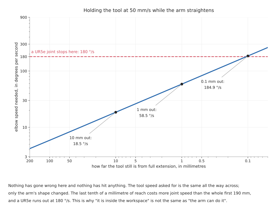
At 10 mm from full extension the elbow needs 18.5 degrees per second, which is nothing. At 1 mm it needs 58.5. At a tenth of a millimetre it needs 184.9, and the official Universal Robots description caps every UR5e joint at 180 degrees per second. So the last tenth of a millimetre of reach costs more joint speed than the whole first 190 mm, and on a real arm it is not available at all.
What actually happens on the bench takes one of three forms, depending on what the controller does when the arithmetic asks for more than it has.
The arm slows down. A well-behaved Cartesian controller scales the whole motion back so no joint exceeds its limit. The tool no longer travels at the speed you asked for, which is safe and which breaks any process that depends on speed — welding, dispensing, anything with a flow rate.
The arm lurches. A controller that clamps each joint independently produces a motion that is no longer along the path at all. Near a wrist singularity this shows up as the wrist spinning rapidly through half a turn while the tool barely moves.
The arm faults and stops. Most industrial controllers refuse, which is the honest answer and is the one that gets reported as "the robot will not do the program".
A six-joint arm with a spherical wrist has three families of singularity, and they need to be recognised by sight because they are diagnosed on the bench more often than in software.
| Kind | The configuration | What is lost |
|---|---|---|
| shoulder | the wrist centre lies on the axis of joint 1 | motion in the direction perpendicular to the arm's plane; joint 1 would have to turn infinitely fast |
| elbow | the arm is fully extended, or fully folded | motion along the arm's own length, which is the case drawn above |
| wrist | two of the three wrist axes line up | one rotational degree of freedom; the two aligned joints do the same thing, and their difference is undetermined |
The wrist one is the most common in practice and the most surprising, because nothing about the arm looks extended. It happens whenever the tool points straight along a wrist axis, which is exactly what happens when you ask an arm to point straight down at a table — a request that comes up constantly.
Five situations where a singularity will find you:
- a straight-line move that reaches for something at the edge of the envelope
- pointing the tool straight down at a table from directly above
- any path you generated by interpolating tool poses without checking the joints
- teaching poses by hand, where a person naturally straightens the arm to reach
- a task that needs a full turn of the tool about its own axis
Five situations where it will not:
- joint-space moves between taught poses well inside the envelope
- work confined to a region a third to two thirds of the way out
- a seven-joint arm using its extra freedom to keep the wrist away from alignment
- planning that scores configurations on manipulability, which is a measure of how far a configuration is from being singular
- a mounting that puts the work in front of the arm rather than directly above or below the base
4. Joint limits, and the range that is not there#
Joint limits are simple to state and are the source of two of the least obvious failures in this document.
A joint that can turn more than a full circle makes the planner's problem harder, not easier. Several arms have wrists that travel two full turns. That means the same tool pose corresponds to several distinct joint values, and the planner has to decide which. Get it wrong and the arm unwinds its own wrist in the middle of a task, which is a valid motion and is not what anybody wanted.
A joint whose real range is divided in two produces a search space that is divided in two. This is worth quoting in full, because it is in a file that thousands of projects load without reading. The official Universal Robots ROS 2 description says this about the UR5e's elbow, in config/ur5e/joint_limits.yaml:
we artificially limit this joint to half its actual joint position limit to avoid (MoveIt/OMPL) planning problems, as due to the physical construction of the robot, it's impossible to rotate the 'elbow_joint' over more than approx +- 1 pi (the shoulder lift joint gets in the way). This leads to planning problems as the search space will be divided into two sections, with no connections from one to the other.
Read what that says. The joint's nominal limit is plus or minus 360 degrees. Its physical limit is about plus or minus 180, because the shoulder gets in the way. If the planner is told the nominal figure it explores a space in two disconnected halves and behaves badly, so the description file tells it the physical figure instead. The decision is correct. The consequence is that half the elbow's nominal travel is invisible to every planner that loads this file, and nothing anywhere reports that.
That is the general shape of the problem. The limits the planner sees come from a description file, and a description file is a claim about the arm rather than the arm. Three ways it drifts from the truth:
- a limit narrowed deliberately, as above, for a reason that was true then
- a limit that does not account for the tool, the cable, or the dress pack, all of which reduce the real range
- a limit that is right for the joint and wrong for the pair, because two joints that are each within range can still collide with each other
Five things a joint limit stops you doing that are easy to miss:
- following a circular path that requires the wrist to keep turning the same way
- approaching the same object from two sides without an intervening reset
- executing a taught programme after the tool has been changed for a longer one
- reaching a pose that inverse kinematics found, because the solver was not told about the limits
- reversing a path, because the way back can need a joint value the way out did not
5. Configurations: the eight ways to reach the same pose#
For a six-joint arm with a spherical wrist — which is most industrial arms — a given tool pose generally has eight distinct joint solutions. They come from three independent binary choices.
Shoulder, left or right. The arm can reach the same point with the base turned towards it or turned away from it and reaching backwards over its own shoulder.
Elbow, up or down. The classic pair. Same wrist position, elbow above or below the line from shoulder to wrist.
Wrist, flip or no-flip. The wrist can be turned through half a turn on joints 4 and 6 while joint 5 changes sign, which puts the tool in the same place pointing the same way.
Two by two by two is eight. Every one of them is a correct answer to "where do I put the joints", and they are not interchangeable:
- they have different distances to the joint limits
- they have different distances to a singularity
- they collide with different things
- the arm cannot generally get from one to another without passing through a singularity, which is the reason it matters
That last point is the one to hold on to. The eight solutions are not eight points in a connected space you can slide between. They are, for practical purposes, eight separate regions. A path that starts elbow-up and ends elbow-down has to straighten the arm completely somewhere in the middle, and a planner will either refuse or produce a motion that alarms whoever is watching.
This is where an early choice makes a later step impossible, and it is worth being concrete. Suppose a pick-and-place: reach into a bin, grasp a part, place it in a fixture. The grasp is chosen first, because the part's pose decides it. That grasp has eight joint solutions and the planner picks one — usually the one nearest the current configuration, which is a reasonable default and is not a decision anybody made. Now the place pose is planned, and from that configuration the only solutions for the place are on the other side of a joint limit. The place fails. Nothing was wrong with the grasp, nothing was wrong with the place, and the error message will be about the place.
The fix is in section 9 of planning a path, and it is not a framework. It is to solve the whole chain before committing to the first step of it.
Five jobs where configuration choice is the whole problem:
- any task with a fixed approach direction, such as inserting into a machine
- palletising, where the same motion repeats at many positions and must not flip configuration halfway across the pallet
- a cell with a wall or a fence on one side, which makes one shoulder solution illegal everywhere
- bin picking, where the grasp pose varies and the configuration must not
- any task where a person watches, because a configuration flip looks exactly like a malfunction
Five jobs where it does not matter:
- a single move between two taught poses in the middle of the envelope
- work on a small, flat region where all eight solutions are far from limits
- a seven-joint arm with a null-space policy, which handles it continuously
- teaching and replay, where the configuration is recorded along with the pose
- simulation with no joint limits modelled, which is why the problem is usually discovered on hardware
6. Redundancy, and the seventh joint#
Six numbers describe a pose: three for position, three for orientation. An arm with six joints has exactly enough freedom to hit a pose, and generally a finite number of ways to do it. An arm with seven joints has one more than it needs, and therefore an infinite family of joint solutions for the same tool pose — a continuous one-dimensional set you can slide along without the tool moving at all. That set is called the null space, and sliding along it is usually described as the elbow swinging round while the hand stays put.
What the extra joint buys you:
- it can hold the tool still while moving the elbow out of the way of an obstacle
- it can hold the tool still while moving away from a joint limit
- it can hold the tool still while moving away from a singularity
- it can serve a secondary objective continuously, rather than by choosing between eight discrete options
- it makes a configuration flip unnecessary, because there is a continuous route between solutions that a six-joint arm would have to jump between
What it costs:
- inverse kinematics no longer has a closed-form answer, so you are solving numerically and the solution depends on where you started
- the null-space policy becomes part of your system, and a policy nobody chose is still a policy
- repeatability of the configuration is lost: the same tool pose commanded twice can give two different arm shapes, which matters near obstacles
- a joint more is a motor more, a brake more, and a failure mode more
- it is harder to explain to anybody signing off the cell
Seven-joint arms include the Franka research arms and Kinova's Gen3. Six-joint arms include the whole Universal Robots range and most of what is installed in factories. The choice is not about capability in the abstract; it is about whether your cell has obstacles the arm has to reach past.
7. Where to bolt the arm down#
This is the cheapest decision in the whole area and the most expensive to reverse. It is usually made by whoever built the bench.
Four things the mounting decides, in rough order of how often they are overlooked.
How much of the workspace is usable. Bolt the arm in the middle of a table and the region directly above the base — the hole from section 2 — sits over the most convenient part of the table. Mount it at the edge, facing in, and the hole is off the table.
Whether the arm can reach a pose in a good configuration or only a bad one. The same point can be well inside the dexterous region for one mounting and right at the singular edge for another. Moving the base 150 mm is often the difference between a task that works and a task that needs a seven-joint arm.
What the arm collides with. An arm mounted upright collides with its own table when reaching low. An arm mounted on a wall or inverted on a frame does not, which is why so many production cells hang the arm upside down.
Gravity, and therefore payload and force control. An inverted arm carries its own weight differently, and its gravity compensation model must know which way up it is. This is a configuration item, and getting it wrong shows up as an arm that drifts when you enable compliance.
The table below is the three usual mountings against what each is for. Read the last column as the reason people regret it.
| Mounting | Suits | Regretted because |
|---|---|---|
| upright on a bench | most table-top work, teaching, anything a person stands beside | the hole sits over the best part of the bench, and reaching low means reaching around the base |
| inverted on a frame | dense cells, machine tending, anything needing reach down onto a surface | everything is harder to reach by hand, and the frame is in the way of a person |
| on a wall or a pillar | long reaches across a bench, keeping the bench clear | the reachable region is a half-space, so half the eight configurations are unavailable everywhere |
One further point that is specific enough to be worth naming. Deciding the mounting requires knowing the task poses, and deciding the task poses requires knowing the mounting. The way out is to compute a reachability map for two or three candidate mountings before anything is bolted to anything, which is the subject of the next section and takes an afternoon.
8. Finding out before you commit#
There are four levels of answer here and they cost wildly different amounts. Take the cheapest one that settles your question.
Arithmetic on the link lengths. The inner and outer radii, worked out by hand. Costs nothing, answers only the crudest question, and rules out more bad layouts than people expect.
Inverse kinematics on every pose you care about. Write the list of poses the task needs, ask the solver for each, and count the failures. Costs an hour and answers the second and third of the four questions in section 1. This is the step most projects skip and it is the one with the best return.
A reachability map. Sample the volume in front of the arm on a grid, try many orientations at each point, and record what fraction succeeded. The result is a picture of where the arm is genuinely comfortable, and it makes the mounting decision for you. reach, from ROS-Industrial, is the maintained tool for this and is Apache-2.0. It was last pushed in March 2025, so it is stable rather than active. The older and better-known Reuleaux has been moved into ROS-Industrial's attic, was last touched in July 2024, and carries no licence file at all, which under default copyright means no permission to use it for anything. It is worth knowing the name because papers cite it, and it is not worth building on.
Running the planner. The only thing that answers the fourth question. Costs the most and is the only honest test of "can the arm get there from here".
8.1 The solver's answer is weaker than it looks#
One detail matters more than everything else in this section, because it makes the second and third levels above unreliable if you take them at face value.
MoveIt's default inverse kinematics solver is KDL, which is iterative. It starts
from a seed, steps towards the goal, and gives up when it runs out of time. The
time it is given is the kinematics_solver_timeout parameter, and its default
value in MoveIt is 0.05 seconds.
So when a reachability check reports a pose as unreachable, what it has actually established is: no solution was found within 50 ms, starting from the seeds this run happened to try. That is not the same statement as "no solution exists", and the two are reported identically. Poses near the edge of the workspace, and poses that need an unusual configuration, are exactly the ones a seeded iterative solver is worst at, and they are exactly the ones you are testing.
Three practical responses:
- raise the timeout when you are surveying rather than executing; 50 ms is a runtime figure, not a survey figure
- retry from several seeds and count how many succeed, which turns a yes-or-no answer into a measure of how marginal the pose is
- use a solver with a different failure mode when it matters. TRAC-IK (BSD-3) exists because KDL fails on poses that have solutions, and it runs two methods in parallel and takes whichever answers first. pick_ik (BSD-3) is the maintained modern alternative inside MoveIt and is under active development.
9. Cheap tests before expensive ones#
Section 8 put four ways of answering the reachability question in order of what they cost. Section 8.1 then showed that the expensive answer is also the least trustworthy one, because "unreachable" turned out to mean "not found in fifty milliseconds". Both of those are cases of a more general idea, and the general idea is worth stating on its own, because it changes the shape of the code rather than one parameter in it.
A planner charges you the same whether the answer is yes or no. Every request costs milliseconds or seconds, and a request that fails costs the most, because a planner that cannot find a route spends its whole time budget discovering that. Meanwhile most of the candidate poses a real system produces can be thrown away by arithmetic that costs nanoseconds. So the rule is to put your tests in order of what they cost, run the cheap ones first, and never ask an expensive question about a candidate that a cheap question could have rejected.
9.1 The order, and what each test costs#
The table below is that order, cheapest first. The second column is what one
candidate pose costs. The first four figures are measured: a loop over two
million candidates written in C, compiled with cc -O2 on an Apple M4, with
twenty obstacles in the scene for the two tests that need them. They are
per-candidate costs inside a batch, which is how a filter is actually run. The
last two figures are not measurements but budgets — the default time MoveIt
allows one call before it gives up — because what you must plan against is the
failing call that uses all of it. Read the last column as the reason the row
below it still has to exist.
| Test | Cost per candidate | What it rules out | What it cannot see |
|---|---|---|---|
| approach direction, against the cone the task allows | 0.2 ns | grasps that come in from a direction the task forbids | whether the arm can achieve that direction at that place |
| distance from the shoulder, against the reach envelope | 0.4 ns | points no joint configuration can put the tool at | orientation, obstacles, and everything else |
| clearance, distance to the nearest obstacle | 10 ns | poses with no room for the gripper's own body | contact along the approach, and the arm's own links |
| line of sight, a ray against the known obstacles | 49 ns | viewpoints from which the target is hidden | anything the world model does not contain |
| inverse kinematics | up to 50 ms | poses with no joint solution | collisions, unless a planning scene is attached |
| a motion plan | up to 5 s | goals with no route from where the arm is now | nothing |
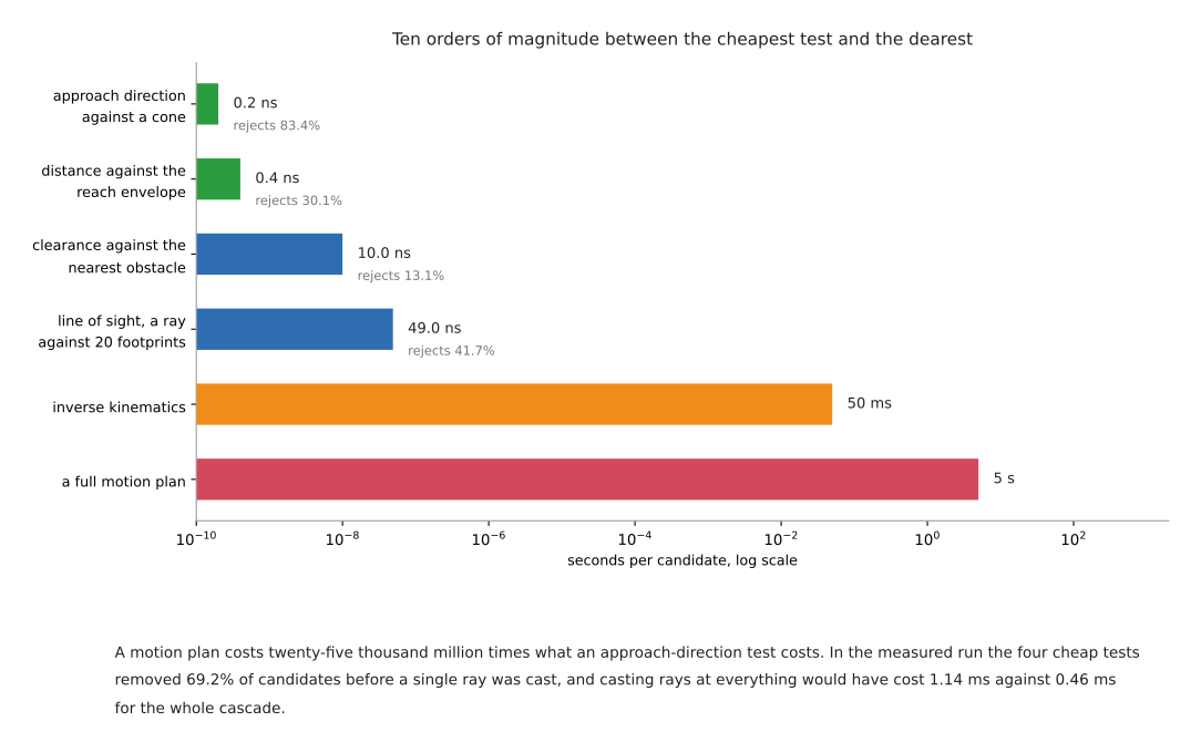
The two ends of that order are ten orders of magnitude apart. Fifty milliseconds of inverse kinematics is 125 million times the 0.4 nanoseconds of the reach test. Five seconds of planning is 102 million times the 49 nanoseconds of a ray cast, and 25 thousand million times the 0.2 nanoseconds of the approach cone. Put the other way round: in the time one failing planning request takes, the reach test can be run on about twelve thousand million candidates.
Those figures come from one machine and one compiler, and a single isolated call costs more than a call inside a loop. None of that matters, because the decision they support only needs the orders of magnitude to be right, and ten orders of magnitude survive any amount of measurement error.
One refinement changes the order in some scenes. The right thing to sort by is not cost on its own but cost divided by the fraction of candidates the test rejects, smallest first, because a test that costs twice as much and rejects five times as many candidates should go earlier rather than later. In the run above, the approach cone rejected 83.4 per cent of candidates, the reach test 30.1 per cent, the ray cast 41.7 per cent and the clearance test 13.1 per cent. Dividing through gives 0.24, 1.3, 118 and 76 nanoseconds per rejection, which is the same order that cost alone gives. That is a coincidence of these particular numbers and not a rule, so measure your own rejection rates before deciding you have the order right.
9.2 Reach as arithmetic#
An annulus is the region between two circles that share a centre. Its three-dimensional version, the region between two spheres that share a centre, is what section 2 showed the reachable region to be for a two-link arm. Testing a point against one is three subtractions, three multiplications, two additions and two comparisons.
dx = p.x - shoulder.x
dy = p.y - shoulder.y
dz = p.z - shoulder.z
d2 = dx*dx + dy*dy + dz*dz          # squared, so there is no square root

reject if d2 < r_min_squared or d2 > r_max_squared
The two squared radii are computed once, when the arm is chosen, and never again. The absence of the square root is the reason this costs less than a nanosecond.
The radii come from the arm's published dimensions. Taking the UR5e's official ROS 2 description again, this time config/ur5e/default_kinematics.yaml, the upper arm is 425 mm, the forearm is 392.2 mm, and the three offsets below the forearm are 133.3 mm, 99.7 mm and 99.6 mm. Sampling four hundred thousand random joint configurations puts the tool flange between 33.8 mm and 968.8 mm from the shoulder point.
Do not use the sampled maximum as r_max. A sampled maximum is always an
underestimate, and a test built on it will reject poses the arm can reach. The
figure that is safe is the sum of every offset below the shoulder, because no
chain of links can put its end further away than the sum of their lengths, and
425 + 392.2 + 133.3 + 99.7 + 99.6 comes to 1149.8 mm. That is 181 mm larger than
the sampled envelope, so it rejects fewer candidates, and every candidate it
does reject is genuinely out of reach. Use the sum when the filter must never
be wrong, and use a measured envelope from a reachability map — section 8's
third level — when you have built one and can defend it.
How much work the test does depends entirely on where the candidates come from,
and the difference is larger than people expect. The table below takes the same
annulus, with r_min of 33.6 mm from section 2 and r_max of 968.8 mm, and
applies it to a million points drawn uniformly from four different regions.
Read it as a warning against assuming the test is doing work it is not doing.
| Where the candidate positions come from | Fraction the reach test rejects |
|---|---|
| a 2.0 by 2.0 by 0.6 m cell centred on the arm | 30.1 per cent |
| a 2.0 by 1.6 by 0.6 m area in front of the arm | 56.3 per cent |
| a 1.2 by 0.8 by 0.3 m bench in front of the arm | 0.3 per cent |
| a 0.3 m bin standing 0.5 m from the base | 0.0 per cent |
A filter that rejects nothing is still worth keeping at 0.4 nanoseconds, but it is not the thing protecting your cycle time, and believing otherwise is how a pipeline ends up with no protection at all.
Two limits on the test are worth naming. The reachable set is not really an annulus: section 2 showed the UR5e has a second hole, 33.6 mm wide, around its own base axis, and a radial test from the shoulder does not model that at all. And passing the test says nothing about orientation. The dexterous workspace from section 1 — the positions reachable with every tool direction — is a much smaller region inside the same annulus, so a point can pass the reach test and still have no solution with the direction the task requires.
9.3 Line of sight is a precondition, not a difficulty#
A ray cast is the test of whether the straight line from one point to
another passes through anything. For a camera looking at a grasp, the two
points are the lens and the target, and the things in the way are the objects
the perception system has already found. Testing the segment against a circular
footprint is a projection, a clamp and one comparison of squared distances, and
twenty of them came to 49 nanoseconds above. For a full three-dimensional
occupancy map, OctoMap provides the same
test, as a method called castRay, and its library is under the three-clause
BSD licence, read from octomap/LICENSE.txt in the repository.
Choosing viewpoints properly is a subject of its own, and choosing where to look in the perception area treats it as one. The point that belongs here is narrower and is about movement.
Visibility and reachability are independent filters, and both are cheaper than planning. A viewpoint can be comfortably inside the arm's envelope and see nothing, because a box is in the way. A viewpoint with a completely clear view of the target can be outside the envelope entirely, or inside it and only reachable in a configuration that puts the elbow through the bench. Neither test predicts the other, so neither can be skipped, and running both still costs about fifty nanoseconds against a planner call's milliseconds. The mistake this prevents is the common one of treating occlusion as something the planner will sort out. It will not. It will plan a perfectly good motion to a pose from which the camera sees a box.
9.4 Clearance is a precondition too#
Clearance is the free space a gripper needs around the object before its fingers can close on it, and how much it needs follows from the jaw geometry. The gripping area derives that properly in choosing a grip, which is where the numbers belong. The movement-side point is that the derived figure is a distance, and a distance can be tested against a scene by arithmetic, long before anything is asked to plan.
The test is the same shape as the reach test: for each obstacle, compare the squared distance from the grasp point to the obstacle against the squared sum of the obstacle's radius and the clearance the gripper needs. Twenty obstacles came to 10 nanoseconds above.
A pipeline that collision-checks only the final pose will miss this. The closed grasp pose is a pose in which the fingers are around the object and touching nothing, so it passes. What fails is the open gripper arriving: the jaws are wider apart on the way in than they are at the end, and the last hundred millimetres of the approach sweeps a volume that the final pose does not occupy. Checking the goal and not the approach is one of the reasons a grasp that looked fine in simulation knocks its neighbour over on the bench.
When you do want the exact answer rather than the cheap one,
FCL is the library
MoveIt's default collision checking is built on. It answers distance queries as
well as collision queries, and a distance query is what clearance needs. It is
under the three-clause BSD licence, read from its LICENSE file.
9.5 What the cheap tests cannot tell you#
They fail in two directions and the two are not equally dangerous.
A conservative bound produces false negatives, and they are silent. The 1149.8 mm figure above is correct and loose. Any candidate it rejects is genuinely unreachable, but a tighter bound you cannot prove would have rejected more, and a looser one rejects fewer. The cost of getting this wrong in the safe direction is work you did not need to do. The cost of getting it wrong in the other direction is a rejected candidate that was fine, never looked at again, and never reported, because a filter that discards a candidate writes nothing anywhere.
An incomplete world model produces false positives, and those are the ones that break things. Every test in this section is a test against a model of the scene, not against the scene. The model does not contain the cable, the clamp somebody left on the bench, the second object that moved after the last camera frame, or the operator's hand. A candidate that passes every cheap test and then collides is a candidate the model said was fine, and no amount of making the tests cheaper or faster addresses that.
The rule that follows is short. Write the cheap tests so they can only ever reject. A rejection from a sound bound is a real answer. An acceptance is not an answer at all; it is permission to ask the next, more expensive question. The cheap tests raise how many candidates you can consider. They do not replace the collision check on the trajectory that is actually going to be executed, and a system that treats them as though they do has moved its failures from the planner, where they were reported, to the hardware, where they are not.
9.6 A worked ordering#
A candidate grasp pose arrives from whatever produced it — a grasp sampler, a model, a taught list — and passes through the filters in cost order. The cost against each line is per candidate, measured for the cheap ones and budgeted for the expensive ones, as in the table above.
# one candidate grasp pose, filtered cheapest test first

# 0.2 ns: approaching from a direction the task forbids
if dot(candidate.approach_axis, task.required_axis) < cos(task.tolerance):
    reject

# 0.4 ns: outside the reach envelope
dx, dy, dz = candidate.position - arm.shoulder_point
if not (r_min_squared <= dx*dx + dy*dy + dz*dz <= r_max_squared):
    reject

# 10 ns for twenty obstacles: no room for the gripper's own body
for each obstacle in scene:
    need = obstacle.radius + jaw_clearance
    if squared_distance(candidate.position, obstacle) < need*need:
        reject

# 49 ns: the grasp cannot be seen from where the camera is
if ray_hits_anything(camera.position, candidate.position, scene):
    reject

# 49 ns: the approach itself is blocked
if ray_hits_anything(candidate.approach_start, candidate.position, scene):
    reject

# up to 50 ms: no joint solution was found, which is not the same
# as none existing -- section 8.1
q = inverse_kinematics(candidate.pose,
                       seed  = arm.current_joints,
                       valid = not colliding in the planning scene)
if q is None:
    reject

# up to 5 s: no route from where the arm is now. This is the call
# every line above it exists to avoid making.
plan = motion_plan(arm.current_joints, q)
if plan is None:
    reject

return plan
Three things in that sequence are the reason for writing it out rather than describing it.
The clearance test comes before both ray casts, and that is deliberate. A ray cast costs 49 nanoseconds and the clearance test costs 10, so putting the clearance test first means the two rays are only run on candidates that already have room for the gripper. Here that saves a few tens of nanoseconds and nothing else. It is worth doing anyway, because it is the same reasoning that saves seconds when applied to the bottom two lines.
The collision check happens inside the inverse kinematics call. MoveIt takes a validity callback, so the solver rejects a colliding solution and keeps searching instead of returning one you then have to discard. The second and third questions in section 1's table are answered by one call, and that call was going to be made anyway.
The last two lines carry almost all of the cost and they are the only two that answer the question. Everything above them is a way of reaching them less often. Nothing above them can tell you a path exists, and if a candidate reaches the bottom of the list and fails there, no cheap test was wrong — none of them ever claimed it would work.
Five jobs this approach suits:
- bin picking, where a grasp sampler produces hundreds of candidates per camera frame and there is time to plan for perhaps three of them
- deciding where to stand a mobile base, or where to bolt a fixed one, which is a search over hundreds of base positions with every task pose to check at each
- deciding which of several objects on a table to reach for first, where most of the answer is which ones are reachable and visible at all
- choosing where to move a wrist camera, where a large majority of candidate viewpoints are either blind or out of the envelope
- any cell with a cycle-time budget, where the planner gets one attempt and a failed attempt spends the budget without producing anything
Five jobs it cannot do:
- tell you a path exists, which is the fourth question in section 1 and which only a planner run for real answers
- see anything the world model does not contain, which is where the failures that hurt come from
- choose between two candidates that both pass, because a filter sorts nothing and every survivor looks identical to it
- catch the failure in section 2, where both ends of a move pass every test and the middle of it is outside the workspace
- replace the collision check on the trajectory that will actually run, which stays exactly where it was
10. The five failures that do not announce themselves#
Collected here because they are the return on reading this document.
The straight line between two reachable poses is not reachable. Section 2. Both ends check out; the middle does not. Nothing in a per-pose check can see it.
"Unreachable" means "not found in 50 milliseconds". Section 8.1. A survey built on the runtime default will mark good poses as bad, and the marginal poses are the ones it gets wrong.
The joint limits in the description are not the joint limits of the arm. Section 4. The UR5e's elbow is deliberately halved in the file everybody loads. The decision is right; the silence about it is the problem.
The grasp you chose decided the configuration, and the configuration decided that the place is impossible. Section 5. Both plans succeed on their own. The failure appears at the second step and was caused by the first.
The dexterous workspace is much smaller than the workspace, and every tutorial's example pose is in the middle of it. Section 1. A task developed on poses 400 mm in front of the arm will work. The same task at 700 mm, with the tool pointing sideways, may have no solution at all, and the first symptom will be a planner that times out rather than a message about orientation.
Next: planning a path, which assumes the goal is reachable and asks how to get to it. Or back to the overview.