This page explains the software layer that watches every command on its way to the arm and stops or limits the ones that are unsafe. It answers five questions. What does the layer check, and how does each check work with real numbers? How do you check the commands of a learned policy, which can output anything, and what happens when the commands stop arriving? And what is this layer not, meaning where does it stop and where must certified safety equipment take over?
It is written for a reader who has read the PID control and
trajectory generation pages, or who already knows
what a joint limit and a speed limit are. It also helps to have read the
sensor streams
page, because a safety check is a threshold on a stream. Every number on this
page comes from a real run of the diagram script,
docs/diagrams/sensor_streams_and_safety.py.
Read this first. Nothing on this page is a certified safety function, meaning one that has been designed, tested and approved to a safety standard and that runs on hardware built for it. The software layer described here runs on an ordinary computer, in ordinary code, so it catches mistakes and makes the arm better behaved. But it must never be the only thing between the arm and a person, and section 7 draws that line in full.
Contents#
- What this page answers
- The idea in one sentence
- How it works, step by step · Where the layer sits · Joint limits and clamping · Checking a learned policy's commands · Workspace boxes and keep-out zones · A watchdog for commands that stop arriving · Speed and separation monitoring · Power and force limiting · The steps as pseudocode
- Where it is used on a robot arm
- Where it is useful, and where it is not
- Libraries that provide it
- This is not a certified safety function
- Why a software safety layer, and what it costs
- The learned alternative
- Where to read next
- Using it in Python
1. What this page answers#
An arm does whatever its commands say, and those commands come from a planner, a teleoperation joystick, a visual servo loop or a learned policy. But any of them can be wrong. For example, a planner can be given a bad goal, a network cable can drop, and a learned policy can output a target a metre away for no reason anyone can see.
Because of that, a safety monitor is a small piece of code placed between the command sources and the arm's controller. It checks every command against a list of rules, and if a command breaks a rule, the monitor limits it, refuses it, or stops the arm. It also watches the arm's sensors, so it can stop the arm when something is happening that no command asked for.
Those rules fall into six groups, and section 3 takes them in turn.
- Joint position, speed and torque limits.
- Checks on a learned policy's output.
- A workspace box, and keep-out zones inside it.
- A watchdog that stops the arm when commands stop arriving.
- Speed and separation monitoring: slowing down as a person comes closer.
- Power and force limiting: keeping contact gentle.
2. The idea in one sentence#
Since those six groups of rules all do the same kind of job, here is that job in one sentence. Check every command against simple, fixed rules just before it reaches the arm, and when a rule is broken, prefer stopping and saying so over quietly changing the command.
Here is an everyday example of the same idea, a driving instructor's car with a second brake pedal on the passenger side. The learner does the driving, while the instructor does not steer and does not try to drive better than the learner. Instead the instructor watches for a few simple things: too fast, too close, the wrong side of the road. When one of them happens, the instructor brakes. But that second pedal is not a replacement for seat belts and airbags, which work even if both people make a mistake. So a safety monitor is the instructor's pedal, while the certified safety functions in section 7 are the seat belts.
3. How it works, step by step#
Where the layer sits#
Because the monitor has to see every command, it sits after every command source and before the controller. The Book 3 page on controlling the move describes that controller layer in ROS 2, and two facts from that page matter here.
- The standard trajectory controller checks less than people assume. Its tolerances default to zero, and zero means "do not check". So by default nothing compares where a joint is with where it should be during a move. Its section 3 explains this. A monitor that checks the following error, the gap between the commanded and the measured position, fills that gap.
- Speed scaling is a request, not an enforcement. Its section 8 says so. A software speed limit is also a request, only a more careful one. Enforcement belongs to the certified functions in the robot's own controller.
The monitor runs at the control rate, often 100 to 1,000 times a second. So each check must take a tiny, fixed amount of time, which is why the checks are kept simple: comparisons, clamps and a few multiplications.
Joint limits and clamping#
The simplest rules are the ones about a single joint. Every joint has a range it can move through, a top speed, and a largest torque, where a torque is a turning force measured in newton metres (N m). The arm maker gives the hardware limits, so a monitor uses software limits set a little inside them, and the software then stops the joint before the hardware has to.
There are two ways to apply such a limit. Clamping replaces a value outside the range with the nearest value inside it, while refusing rejects the command, keeps the arm where it is, and reports a fault. So clamping keeps the arm moving, whereas refusing tells you that something is wrong. Book 1's joint class shows both, and the Book 3 gripper pages prefer refusing when a force cap is exceeded.
A speed limit is applied by rate limiting, which means the target may move at
most speed limit × time step from one tick to the next. At 2.5 rad/s and 100
ticks a second, that comes to 0.025 rad per tick.
Checking a learned policy's commands#
The joint limits above apply to any command source, but one source needs more care than the rest. A learned policy is a neural network that turns camera pictures and joint angles into commands, and Book 7's movement models chapter describes them. Unlike a planner, a policy has no built-in idea of the arm's limits or of obstacles, and Book 3's learned motion page lists what it lacks. So its output must be checked every single time.
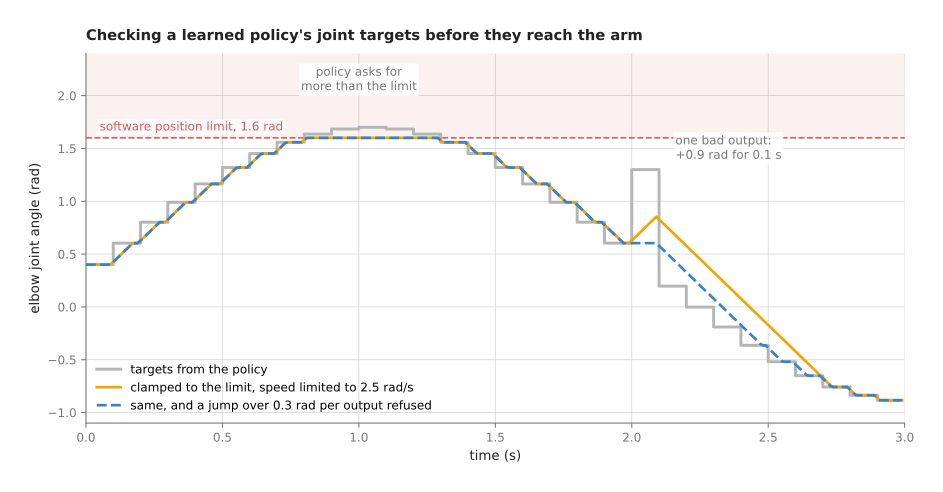
The picture below shows one elbow joint driven by such a policy. The policy sends a new target 10 times a second, while the monitor runs 100 times a second.
Two things go wrong in the policy's output.
- Around 1 s, it asks for up to 1.70 rad, past the 1.6 rad software limit. Both monitored versions clamp this, and the joint stops at 1.60 rad.
- At 2.0 s, one output jumps 0.9 rad above its neighbours for 0.1 s. The biggest step in the raw targets is 1.10 rad in one tick.
The orange line clamps and rate limits, so it never moves faster than 2.5 rad/s and its biggest step is 0.025 rad per tick. But it still moves towards the bad target, and the joint goes 0.25 rad (about 14 degrees) the wrong way before the next good output arrives. In other words, rate limiting has turned a jump into a smooth, believable mistake.
The blue dashed line adds one more rule, because it compares each new output with the last good one. A step of more than 0.3 rad per output is refused, so the joint holds the last good target and a fault is logged. As a result it logs exactly one fault, at 2.0 s, and the joint never moves towards the bad target.
This is why a monitor for a learned policy checks more than the limits. The usual checks are these.
- The output is a real number: no NaN (not a number) and no infinity.
- The output is fresh: its time stamp is recent, so it was computed from a recent picture.
- Each joint target is inside its limits.
- The step from the last accepted output is small enough.
- The tool position it implies is inside the workspace box and outside every keep-out zone. The tool position is computed from the joint targets with forward kinematics.
- The expected force is within limits, and the measured force is too.
Book 7's safety checks around a model gives the same list from the model's side.
Workspace boxes and keep-out zones#
The checks so far were all on joint angles, but some rules are easier to state in the space the tool moves through. A workspace box is a region the tool must stay inside, while a keep-out zone is a region inside that box which the tool must never enter, such as a camera stand, a fixture, or the part of the table where a person works. Both are usually boxes, because the check is then only a few comparisons.
But the tool is not a point, so each check treats the gripper as a sphere around the tool point, 40 mm in radius here. That is the same as moving the box's walls in by 40 mm and the keep-out zone's walls out by 40 mm.
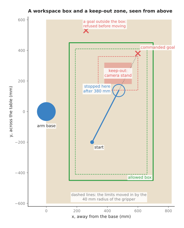
In the picture, the box runs from 150 to 700 mm away from the base and from −450 to 450 mm across, while the camera stand's keep-out zone runs from 380 to 560 mm and from 180 to 320 mm. A command asks the tool to go in a straight line from (300, −200) to (600, 380), and the whole path is 653 mm long. The goal itself is inside the box, so a check on the goal alone would pass it.
Instead the monitor checks points every 5 mm along the path. At 380 mm the gripper's sphere would come within 40 mm of the keep-out zone, so the monitor stops the tool there, at (475, 138). A second goal, at (260, 530), is outside the box altogether, so it is refused before the arm moves at all.
A path planner with a collision model also avoids the camera stand, as the planning and search chapter explains. But the monitor is still useful, because it also checks the commands that did not come from the planner: a joystick, a servo loop, a policy.
A watchdog for commands that stop arriving#
The checks above all assume that commands keep arriving, but many command sources send a stream, such as "move at this speed" 100 times a second. So if the sender freezes or the network drops, the last command may stay in force, and the arm then keeps going at the last speed.
Because of that, a watchdog is used, which is a timer that every new command resets. If the timer runs past a timeout with no new command, the watchdog stops the arm. The name comes from a dog that barks when it stops hearing its owner.
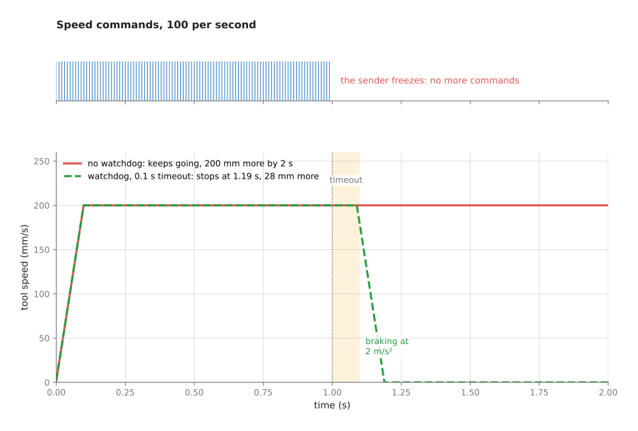
In the picture the tool is commanded at 200 mm/s, and the sender freezes at 1.0 s. Without a watchdog the tool has moved 200 mm further by 2.0 s, and it would keep going until something else stopped it. But with a 0.1 s timeout and braking at 2 m/s², the tool stops at 1.19 s, 28 mm after the last command arrived.
The timeout itself is a trade. A short one stops the arm sooner, but it also stops it whenever the computer is briefly busy, so a common choice is a few times the normal gap between commands. The braking distance after the timeout must also fit inside the free space around the arm.
A watchdog can also run in both directions, because the arm's driver watches the computer while the computer's monitor watches the arm's state messages. So if the state messages stop, the monitor cannot see the arm, and it should stop sending motion.
Speed and separation monitoring#
The rules so far protected the arm and the work, but two of the six groups are about people. Speed and separation monitoring slows the arm as a person comes closer, and stops it when the person is too close, so it needs a sensor that measures where people are, such as a laser scanner on the floor or a camera above the cell.
The rule itself comes from one question: if the person walked straight at the arm now, could the arm stop before they met? The gap needed is the sum of four distances:
- how far the person walks while the system notices and while the arm brakes;
- how far the arm moves before it starts braking;
- how far the arm moves while braking;
- a margin for sensor error and the size of a hand or arm.
The picture below uses illustrative numbers, not numbers from any standard. The person walks at 1.6 m/s, while the sensor and software take 0.1 s to react. The arm brakes at 2 m/s², the margin is 0.1 m, and the arm's top speed is 0.5 m/s.
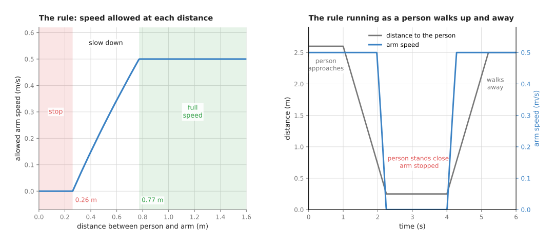
At full speed the arm needs a gap of 0.77 m, and at a standstill it still needs 0.26 m, because the person keeps walking while the system reacts. In between, the monitor chooses the highest speed whose gap fits, so at 0.6 m that is about 0.34 m/s. On the right, a person walks up from 2.6 m, and the arm starts slowing at 1.98 s and is stopped at 2.25 s, when the person is 0.25 m away. Then when they walk away, it speeds up again.
A software version of this is useful for keeping a cell running smoothly. But the version that protects people must use a safety-rated sensor and a safety-rated controller, with the distances and speeds worked out by the method in the standards, and section 7 says more about that.
Power and force limiting#
Instead of keeping people away, power and force limiting is the other way to work near them. The arm is allowed to touch a person, but only gently, so that the force and the pressure of any contact stay below set values. Collaborative arms, often called cobots, are built for exactly this, because they are light, have rounded shapes, and sense force in their joints or estimate it from the motor currents.
Two things decide how hard a contact is. The first is the force the controller is pushing with, and the impedance and force control page shows how to cap it. The second is the energy of the moving arm when it meets something, and that kinetic energy grows with the square of the speed. A moving mass of 2 kg at 0.25 m/s carries 0.0625 J, while at 1 m/s it carries 1 J, sixteen times as much. This is why power and force limiting always comes with a speed limit as well.
A software force monitor watches the wrist force, or the gap between the expected and the measured joint torques. It uses a filtered signal, a threshold with hysteresis, and a short debounce, as the sensor streams page explains. But the debounce must be short, because every millisecond of waiting lets the force grow further. Book 7's collision and failure detection page covers the expected-against-measured torque method, and the learned versions of it.
The steps as pseudocode#
every control tick (for example 100 times a second):
    now = current time

    # the watchdog
    if now - last_command.stamp > command_timeout:     stop("no commands")
    if now - last_state.stamp   > state_timeout:       stop("cannot see the arm")

    cmd = last_command
    # checks on the command itself
    if cmd has NaN or infinity:                        refuse(cmd, "not a number")
    if any |cmd.q - last_good.q| > jump_limit × outputs_since_good:
                                                       refuse(cmd, "jump")
    q = clamp(cmd.q, soft_lower, soft_upper)
    q = last_sent.q + clamp(q - last_sent.q, -v_max × dt, v_max × dt)

    # where the tool would be
    tool = forward_kinematics(q)
    if tool is not inside (workspace_box shrunk by tool_radius):  refuse(cmd, "outside box")
    for zone in keep_out_zones:
        if distance(tool, zone) < tool_radius:          refuse(cmd, "keep-out")

    # what the sensors say
    if |q_measured - q_commanded| > following_limit:   stop("following error")
    if force_flag(filtered_force) is on:               stop("force")
    v_allowed = speed_for_gap(distance_to_nearest_person)
    q = scale step so that tool speed <= v_allowed

    send q; last_sent = q

refuse(cmd, reason): hold last good target, log reason with time stamp
stop(reason):        brake along the path, then hold; log; wait for a person to reset
4. Where it is used on a robot arm#
Because every command source can be wrong in one of the ways above, a software safety layer is used almost everywhere an arm moves under program control. Here are the common places.
- Running a learned policy. Every output is checked for limits, jumps and workspace before it reaches the arm. The first runs are made slowly with a person holding the emergency stop, as Book 7's running a model on a robot page describes.
- Teleoperation. A person steers the arm with a joystick or a second arm. A watchdog stops the arm if the link drops, and a workspace box stops the person steering it into the table.
- Visual servoing. A camera loop sends a new target every picture. A watchdog catches a camera that stops, and a jump check catches a wrong detection.
- Contact tasks. Insertion and polishing run with a force limit that stops the task, not just the motion, when it trips.
- Development and testing. Tight software limits and a small workspace box let people try new code without risking the arm or the table.
- Shared cells. A software speed-and-separation rule slows the arm early and smoothly, so that the certified function, set further in, rarely has to stop it hard.
- Checking the controller's work. A following-error check catches an arm that has hit something, a joint that is slipping, or a controller whose tolerances were left at zero.
5. Where it is useful, and where it is not#
The uses above all point the same way, because the software layer is the right tool for catching mistakes in commands, for keeping a cell running smoothly, and for protecting the arm, the tools and the work. It is quick to change, it can know about the task, and it can report why it stopped.
But it is not the right tool for protecting people on its own. The table below lists the ways it fails. Read each row as one cause, giving the sign you would see and what people use instead or in addition.
| What goes wrong | The sign you would see | What to use instead |
|---|---|---|
| Clamping hides a bad command | the arm moves smoothly, but the wrong way, and no fault is logged | refuse jumps and log them; clamp only small overshoots |
| Limits set too tight | frequent stops during normal work; people start to raise or disable them | measure normal peaks on recordings and set limits with a margin above them |
| The monitor runs on the same computer as the fault | a crash or freeze takes the monitor down too | a watchdog in the arm's own controller; certified functions |
| Only the goal is checked, not the path | the tool passes through a keep-out zone on the way to a legal goal | check points along the path, or the swept volume |
| The tool, a held part or a cable is not in the model | a collision with a part of the gripper the sphere did not cover | larger margins; model what the gripper holds |
| A force threshold on a heavily filtered signal | stops come late and forces overshoot | a short filter for the stop, a long one only for measurement |
| The person sensor misses someone | the arm does not slow | safety-rated sensors, and a cell layout where people cannot reach the arm unseen |
| The monitor is trusted as a safety function | none, until someone is hurt | a risk assessment and certified safety functions, as section 7 explains |
6. Libraries that provide it#
Since most of these checks already exist in the usual tools, the table below lists the well-known ones. Read each row as one tool, giving the languages it is used from, the part that does the checking, and a note on what it covers.
| Tool | Languages | Part | Note |
|---|---|---|---|
| ros2_control | C++ | the joint_limits package | reads position, speed, acceleration and effort limits from the robot description, including soft limits |
| ros2_controllers | C++ | joint_trajectory_controller: constraints and cmd_timeout | tolerances on following and goal error, which default to not checking; a timeout for stale commands |
| MoveIt 2 | C++, Python | moveit_servo | real-time steering with collision checking, singularity slowing, joint limits and a timeout for incoming commands |
| MoveIt 2 | C++, Python | the planning scene | collision objects for keep-out zones at planning time |
| libfranka | C++ | franka::limitRate; Robot::setCollisionBehavior | rate limiting of commands, and the thresholds of the arm's own contact detection |
| the arm maker's safety settings | set on the teach pendant | joint limits, tool speed, force limits, safety planes, stopping behaviour | these run in the robot's own controller; some are safety-rated, check which in the manual |
The last row of that table is the most important one. The arm's own controller usually offers limits of the same kinds as this page, and on collaborative arms some of them are certified, so set those first. The software layer then adds only the checks that your program alone can know about.
7. This is not a certified safety function#
This section draws the line that Book 3 draws in controlling the move: a software limit is a request, and a safety-rated function is an enforcement.
Because of that difference, a safety-rated or certified safety function has four things that the software on this page does not.
- It runs on hardware built for safety, often with two channels that check each other, so that one failed part cannot hide a fault.
- Its design, its failure rates and its tests are documented against a safety standard.
- It keeps working when the ordinary software crashes, freezes or is wrong.
- Its stopping times and distances have been measured on the real arm.
Two standards cover this for robot arms. ISO 10218, in two parts, sets the safety requirements for industrial robots and for the cells they are built into, while ISO/TS 15066 is a technical specification for collaborative robots, where people and arms share a space. Together they describe the ways a person may work with an arm, including a safety-rated monitored stop, hand guiding, speed and separation monitoring, and power and force limiting. They also give the methods for working out separation distances and allowed contact forces. This page does not quote their numbers, so take those from the standards themselves, in their current editions.
Two more things sit outside software entirely. An emergency stop is a large red button wired to cut the motors' power directly, while a risk assessment is a written study of how the cell could hurt someone and what reduces each risk. The standards expect one risk assessment for every cell. The Book 3 one-arm overview notes that the robot safety standards were republished in 2025, which is one more reason to read the current editions.
So the layering is this. The certified functions and the emergency stop are what protect people, while the software monitor on this page protects the arm and the work, catches mistakes early, and keeps the arm away from the certified limits so that they rarely have to trip.
8. Why a software safety layer, and what it costs#
To put all of the above together, a software safety monitor is a set of simple rules that checks every command and every sensor reading just before the arm's controller. This means it gives the arm limits that know about the task, a stop when commands stop arriving, and a clear record of why it stopped.
The obvious alternative is to rely on the arm's built-in safety functions alone. They are essential, and they are certified. But they are set for the arm rather than for your task, so they do not know that a camera stand is on the table, or that a policy's output jumped. And when they act, they usually stop the arm hard, which ends the task. The software layer, in contrast, can refuse one bad command and carry on, slow down smoothly, and say which rule was broken.
A second alternative is to trust the planner. But a planner only checks the path it makes, and it checks nothing else: not a joystick, not a servo loop, not a policy, and not a path that goes wrong while it runs.
The costs are these. Every rule needs a limit, and every limit must be measured and maintained. Limits set too tight cause false stops, and false stops then lead people to loosen or disable them. The checks also add a little delay, and a debounce adds more, while the monitor can fail together with the computer it runs on. But the largest cost is a false sense of safety, because a monitor that works well in testing can make people treat it as a certified function, which it is not.
9. The learned alternative#
Because the value of this layer is that every rule is plain, can be read, and does the same thing every time, there is no learned model that replaces it. Book 6 says the same from the model's side: its safety checks around a model are rules written by people, like the ones on this page. Learned models can add to one part of the layer, the contact checks. Book 7's collision and failure detection page covers detectors that learn the normal gap between expected and measured torque, or notice a dropped object, and says they are worth adding when the textbook model's errors force the stop line so high that gentle bumps are missed. Like this layer, they sit on top of the certified safety function, never instead of it.
10. Where to read next#
- PID control shows torque limits and clamping inside the joint loop.
- Trajectory generation keeps planned motion inside speed and acceleration limits before it is sent.
- Arm dynamics gives the expected joint torques that a force monitor compares with the measured ones.
- Impedance and force control keeps contact forces predictable and shows guarded moves.
- Sensor streams covers the filters, thresholds, hysteresis and debouncing the monitor uses.
- Finite-state machines hold the "running", "paused" and "stopped" states the monitor switches between.
- Book 3's controlling the move covers the ROS 2 controller layer, its tolerances, and speed scaling.
11. Using it in Python#
Section 3 listed the checks a safety layer makes, from joint limits and workspace boxes to a watchdog for commands that stop arriving, and section 7 was clear that none of this is a certified safety function. Section 6 named the tools that already contain these checks, but every one of them is C++ configured from YAML. This section therefore shows the Python you would actually write, so that after reading it you know both the shape of the monitor and why there is no package to install for it.
import numpy as np, time

Q_MIN = np.array([-2.90, -1.76])           # radians, from the arm's manual
Q_MAX = np.array([ 2.90,  1.76])
V_MAX = np.array([ 2.18,  2.18])           # radians per second, from the manual
BOX_MIN = np.array([0.20, -0.35, 0.02])    # allowed workspace, metres, in the base frame
BOX_MAX = np.array([0.70,  0.35, 0.60])
COMMAND_TIMEOUT = 0.1                      # seconds

class SafetyMonitor:
    def __init__(self):
        self.last_command_time = time.monotonic()

    def check(self, q_cmd, q_now, dt, tip_xyz):
        now = time.monotonic()
        if now - self.last_command_time > COMMAND_TIMEOUT:
            return None, "no command for longer than the timeout"
        self.last_command_time = now
        if np.any(tip_xyz < BOX_MIN) or np.any(tip_xyz > BOX_MAX):
            return None, "tool outside the allowed box"
        step = np.clip(q_cmd - q_now, -V_MAX * dt, V_MAX * dt)    # speed limit
        return np.clip(q_now + step, Q_MIN, Q_MAX), None          # position limit
Returning None means "do not move", and the caller then holds the arm where it is or
starts the stop described in section 3. Everything in those twenty lines is yours, and
that is the honest answer for this technique. The only library call is numpy.clip,
which clamps an array between two bounds, and you could write it as a loop.
The tools in section 6 do contain the same checks, but you reach them by configuration
rather than by a Python call. ros2_control's joint_limits package reads the limits
out of the robot description and enforces them inside the C++ controller manager, and
moveit_servo does the collision and singularity checks in C++ as well, with a
cmd_timeout in its YAML file playing the part of COMMAND_TIMEOUT above. So when you
work in ROS 2 the sensible division is to let those tools hold the limits that come
from the arm's description, and to write in Python only the checks that your own
program knows about, such as a keep-out box that exists because of where you put the
conveyor.
What you have to decide or measure is every number in that file, and this is where the work really is. The joint and speed limits come from the arm's manual. The workspace box comes from measuring your cell, and it must be measured in the arm's base frame, because a tool position that your camera reported in the camera frame has to be transformed first or the box will be in the wrong place. The timeout has to be a small multiple of your command period, so that a single late message does not stop the arm while a crashed sender does. And the speed limit needs a reason behind it: section 7 explains that a limit meant to protect a person has to come from a risk assessment and from the numbers in ISO 10218 and ISO/TS 15066, not from what looked smooth on the day.