This page explains how a program finds an object's full pose from one colour picture. The object's pose is where it is and which way it is turned: three numbers for its position and three for its rotation, six in all. Robotics people call this a six degrees of freedom (6-DoF) pose. The method on this page is called Perspective-n-Point, or PnP, and it answers four questions. What does PnP need? How does it find the pose? What happens when some of its inputs are wrong? And why is a flat printed marker hard to read when it faces the camera squarely?
It is for a reader who has read the three pages before this one.
The pinhole camera model turns a point into a
pixel, while rigid transforms describe a pose as a
rotation and a shift. Calibration already uses PnP once, to
find the board in each picture, and this page opens that step up. Every number
on this page comes from a real run of the diagram script,
docs/diagrams/geometry_and_cameras_2.py, with Book 2's camera: 320 × 240
pixels, fx = fy = 277.1, cx = 160, cy = 120.
Contents#
- The idea in one sentence
- How it works, step by step · What goes in and what comes out · Reprojection error, again · A first guess, then refinement · A worked run: the red cube · How many points are needed · Pseudocode
- PnP inside RANSAC: when some matches are wrong
- A flat target, and why face-on is unstable
- Where it is used on a robot arm
- Where it works, and where it does not
- Libraries that provide it
- Why PnP, and what it costs
- The learned alternative
- Where to read next
- Using it in Python
1. The idea in one sentence#
If you know where some points are on an object, and you can see which pixels they land on, there is only one pose of the object that puts all of them on those pixels.
Here is an everyday example. You are lost in a town, but you can see three landmarks you know: a church tower, a bridge and a tall chimney. You know where each one is on your map, and you can also see in which direction each one lies from where you stand. Only one spot on the map gives those three directions at once, so that spot is where you are. Sailors call this "taking a fix".
PnP is the same idea, and the "map" is the object's own shape, written as points in millimetres. The "directions" are the pixels, because each pixel is a direction from the camera, as the pinhole camera model shows. The answer is the object's pose relative to the camera. Turned around, it is also the camera's pose relative to the object, which is exactly what calibration needs.
2. How it works, step by step#
What goes in and what comes out#
Section 1 gave the idea, so this section turns it into a method. PnP needs three things before it can start.
- The object's points, in the object's own frame. For a 6 cm cube, the corners are at (±30, ±30, 0) mm and (±30, ±30, 60) mm, measured from the middle of its base. These come from a drawing, a computer-aided design (CAD) model, or a printed pattern.
- The pixel where each of those points appears. Something else finds these: a corner detector, a marker detector, a feature matcher, or a neural network that finds keypoints. PnP does not look at the picture at all.
- The camera's lens numbers,
fx,fy,cxandcy, and its distortion, which calibration measures.
Each point must be paired with its own pixel, and that pairing is called a correspondence, meaning "this pixel shows that corner". PnP trusts the pairing completely, so section 3 deals with pairings that are wrong.
What comes out is a rotation R and a shift t, which together are the
transform T_camera_object. That transform moves a point from the object's
frame into the camera's frame, and rigid transforms
then carry it into the arm's base frame.
Reprojection error, again#
Suppose you guess a pose. With that guess, you can place each object point in the camera's frame and then project it to a pixel, which is reprojection. The distance between where a point reprojects and where it was really seen is its reprojection error, in pixels, as the calibration page explained.
So PnP is a search for the pose with the smallest reprojection error. It combines the errors of all the points into one number, the root mean square (RMS): square each distance, take the mean, and take the square root. When the pose is right, the RMS is about as large as the noise in the pixels, usually a few tenths of a pixel.
A first guess, then refinement#
Because the projection formula divides by depth, the error is not a simple straight-line function of the pose. So PnP works in two stages, in the same way as calibration does.
- A first guess. A short formula gives an approximate pose directly. The
simplest one is the direct linear transform (DLT). It treats the 12 numbers
of the 3 × 4 matrix
[R | t]as unknowns, writes two straight-line equations for each point, and solves them all at once. It needs six or more points that are not all on one plane, but better formulas exist. EPnP (efficient PnP) needs only four points and is very fast, while P3P (perspective-three-point) uses exactly three. - Refinement. Starting from the guess, the program nudges all six pose numbers at once in the direction that shrinks the RMS fastest, and it repeats until the RMS stops falling. The usual method is Levenberg–Marquardt, the same one calibration uses. It is fast because there are only six unknowns.
The first guess matters, because refinement only walks downhill from where it starts. So if the start is poor, it can settle in the wrong valley, and section 4 shows this happening with flat markers.
A worked run: the red cube#
So here is a real run. Book 2's red box, a 6 cm cube, stands on the table, turned 20°. The camera is the tilted one from the pinhole page: 0.40 m above the table, 0.20 m back from its middle, and looking 60° down. From there it can see six corners of the cube: the four on top and the two bottom corners of the near face.
We projected those six corners with the true pose, then added random noise of 0.3 pixels to each pixel, which is what a good corner detector achieves. Then we gave the refinement a deliberately poor start, with the cube in the middle of the table and not turned. So the picture below shows both the start and the end.
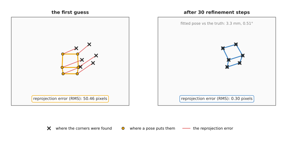
On the left, the orange cube is where the first guess puts the corners, and the red lines are the reprojection errors, whose RMS is 50.46 pixels. On the right, after the refinement, every orange dot sits on its black cross. The RMS fell like this, one step at a time:
| Step | 0 | 1 | 2 | 3 | 4 and after |
|---|---|---|---|---|---|
| RMS reprojection error (pixels) | 50.46 | 5.25 | 0.43 | 0.30 | 0.30 |
Read the table from left to right, because three steps took the error from 50 pixels to the noise level, and the steps after that changed nothing. The final pose was 3.3 mm and 0.51° from the truth. The cube was about 0.47 m from the camera, where one pixel covers 1.7 mm, so 3.3 mm is about what 0.3 pixels of noise on six points allows.
For comparison, the DLT first guess on the same six points gave an RMS of 2.80 pixels, a position 5.1 mm off, and a rotation 4.6° off. The DLT is a good place to start, but not a place to stop.
How many points are needed#
A pose has six unknown numbers, and each point gives two measurements: its u
and its v. So three points give six measurements, which is just enough. But
three points can fit up to four different poses, so a fourth point is needed to
choose between them. In practice:
- 3 points give up to four answers. This is P3P, used inside RANSAC.
- 4 points give one answer, if they are well spread. A square marker has four corners.
- 6 or more points make the answer steady, because the noise averages out.
Points that are close together, or almost in a straight line, give a poor pose even when there are many of them, so spread matters as much as count. The object should also fill a fair part of the picture, because a small object far away gives short distances between its pixels, and the same noise then means a larger turn.
Pseudocode#
So here is the whole of PnP in plain steps. The first-guess formula is named rather than written out, because every library provides one.
inputs: object_points (N points, in the object's frame, in metres)
        pixels        (N pixels, in the same order)
        K, distortion (from calibration)

pixels = undistort(pixels, K, distortion)
R, t = first_guess(object_points, pixels, K)     # DLT, EPnP or P3P

repeat up to 30 times:
    predicted = project(R * object_points + t, K)
    errors = predicted - pixels
    step = the change to (R, t) that shrinks sum(errors²) fastest   # Levenberg–Marquardt
    apply step to R and t
    if the error stopped falling: stop

rms = sqrt(mean(|errors|²))
if rms > about 2 pixels: report failure, do not use the pose
return T_camera_object = (R, t), rms
3. PnP inside RANSAC: when some matches are wrong#
Section 2 assumed that every pairing of a point with a pixel is correct, but in real pictures they are not all right. For example, a feature matcher pairs a pattern on one side of a box with a similar pattern on the other side, and a keypoint model puts a point on a reflection. One wrong pairing can then pull the whole pose away, because refinement tries to satisfy every pairing at once.
RANSAC (random sample consensus) is the standard cure for this. The RANSAC page explains it for lines and planes, and for PnP it works like this.
- Pick a few pairings at random: 3 or 4 for P3P or EPnP.
- Find the pose that those few imply.
- Reproject every object point with that pose. Count the pairings whose reprojection error is under a limit, such as 3 pixels, and those are the inliers, the pairings that agree.
- Repeat many times. Keep the pose with the most inliers.
- Refine that pose using only its inliers.
So we tested this on a printed box, 120 × 80 × 100 mm, with 40 matched features on its top and front faces. Then we gave the true pixels 0.5 pixels of noise. Then we replaced 12 of the 40 pixels, 30 per cent, with random places in the picture. Our RANSAC drew 6 pairings per try, because our simple DLT needs six, and made 200 tries.
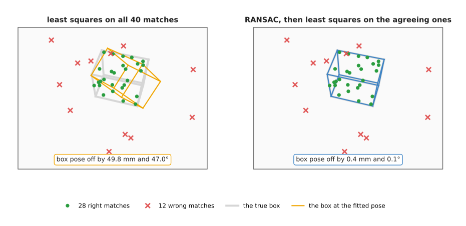
In the picture, the grey box is the truth. On the left, refinement on all 40 pairings produced the orange box, which is 49.8 mm and 47.0° away from the truth and therefore useless. On the right, RANSAC found 28 inliers, and they were exactly the 28 right pairings, so it caught all 12 wrong ones and dropped none of the right ones. The final pose was then 0.4 mm and 0.1° from the truth.
How many tries are enough? A try succeeds when every pairing it draws is right. With 70 per cent right pairings, a draw of 6 is all right with a chance of 0.7⁶, about 12 per cent. To be 99 per cent sure of at least one clean draw, you need about 37 tries. A draw of 4 is all right 24 per cent of the time, and needs about 17 tries. That is why real libraries use four-point or three-point solvers inside RANSAC.
4. A flat target, and why face-on is unstable#
Section 3 dealt with pairings that are wrong, and this section deals with a target whose pairings are all right but whose shape still makes the pose hard. Many robot cells find objects with a fiducial marker, which is a printed black-and-white square, such as an ArUco or AprilTag marker, stuck on the object or on a fixture. Its pattern tells the detector which marker it is and which corner is which, and Book 2 describes them in a marker of known size. So the four corners of the square, with the marker's known size, are exactly a PnP problem with four points on one plane.
Four points on a plane are enough in theory, but in practice there is a trap. When the marker is nearly face-on to the camera, two different poses fit the corners almost equally well, because one is tilted a little towards the camera while the other is tilted the same amount away. The picture shows this for a 40 mm marker, 0.34 m away, tilted 12° one way or the other.
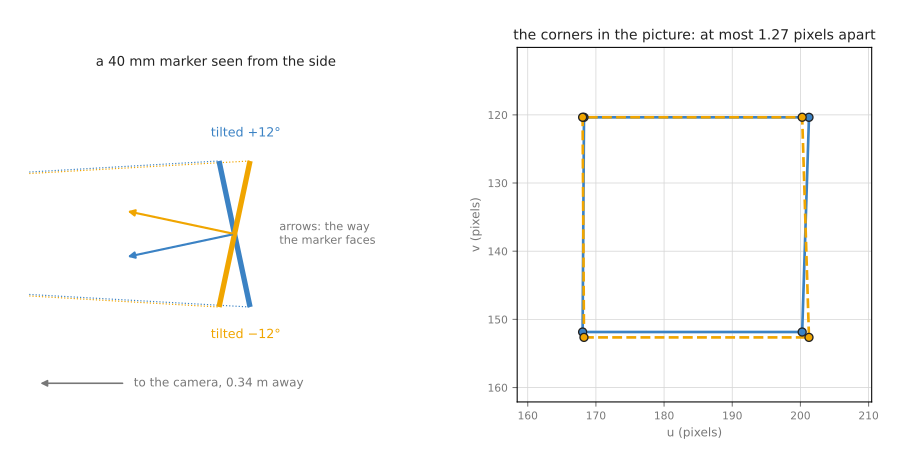
On the left, the two markers are seen from the side, and they face clearly different ways, because the arrows show the direction each one faces, 24° apart. On the right are the four corners each pose puts in the picture, and they differ by at most 1.27 pixels. At 5° of tilt the gap is only 0.53 pixels, so a corner detector with 0.3 pixels of noise cannot reliably tell the two apart.
The reason is perspective. When the marker is tilted, its near edge looks a little longer than its far edge, and that small difference is the only clue to which way the marker tilts. A marker 40 mm wide at 0.34 m covers only 32.6 pixels, so the difference is a fraction of a pixel.
So we measured how bad this is. For each tilt, we added 0.3 pixels of noise to the four corners 300 times, solved each time from both possible starting poses, and kept the one with the smaller reprojection error. This is what the solvers built for squares do, and the chart below shows the error in the direction the marker faces.
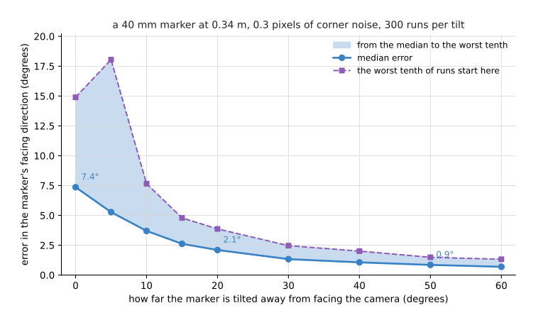
The table gives the same numbers, so read each row as one tilt: the typical error, the error that the worst tenth of runs reached or passed, and how often the solver chose the wrong one of the two poses.
| Tilt | Median error | Worst tenth | Chose the mirrored pose |
|---|---|---|---|
| 0° (face-on) | 7.4° | 14.9° or more | (both poses are the same) |
| 5° | 5.3° | 18.0° or more | 19 per cent of runs |
| 10° | 3.7° | 7.7° or more | 7 per cent |
| 20° | 2.1° | 3.9° or more | 2 per cent |
| 30° | 1.3° | 2.5° or more | none |
| 60° | 0.7° | 1.3° or more | none |
Face-on, the facing direction is typically 7.4° wrong, while at 30° of tilt the same marker and the same noise give 1.3°. The distance to the marker, by contrast, came out about 2 mm wrong at every tilt. A small, face-on marker gives a good position and a poor rotation.
So here is what people do about it in practice.
- Tilt the camera or the marker so that the marker is seen at 20° to 45°, not face-on.
- Make the marker bigger in the picture. A larger marker, or a closer camera, makes the perspective clue larger.
- Use several markers, or a board of them, spread apart. Points that are far apart and not all on one small square fix the rotation well.
- Use the rotation you already know. If the marker is on a flat table, its facing direction is the table's up direction, and only its turn about that direction needs to come from the picture.
- Filter over time. A rotation that flips from frame to frame is the sign of this problem. A Kalman filter or a simple median over a few frames smooths it.
5. Where it is used on a robot arm#
Sections 2 to 4 described the method and its weak spot, and this section says where an arm uses it. PnP runs wherever a program knows an object's shape and can find points on it in a colour picture, and here are the concrete places.
- Reading a fiducial marker. A marker on a fixture, a tray or a rack gives its pose in one picture. Book 3's place-glass case study finds a glass rack this way, with an AprilTag.
- Calibration. Every calibration picture uses PnP to find the board's pose in the camera's frame. Hand-eye calibration then compares those poses with the arm's, as the calibration page shows.
- Keypoint models. A neural network finds named points on an object, such as a mug's handle and rim, and PnP turns them into a pose. Book 7's keypoints and object pose describes this split: the network finds the points, and geometry does the rest.
- Matching against a stored picture. A program stores a picture of a boxed product with the 3D position of each of its features. At run time it matches features in the new picture to the stored ones, then runs PnP inside RANSAC. Image features and matching covers the matching step.
- Checking where the camera is. A wrist camera that sees a fixed marker on the table can check its own pose against the arm's reported pose. A growing difference means the hand-eye calibration has drifted or the camera was knocked.
- Placing a part in a fixture. A part with drilled holes or printed corners gives PnP several well-spread points, and the arm then inserts it.
6. Where it works, and where it does not#
The uses in section 5 all depend on good points and good pairings. PnP is exact geometry, so it fails only when its inputs are wrong or too weak, and the table below lists the common failures. Read each row as what goes wrong, what you see, and what to do.
| What goes wrong | The sign you see | What to do instead |
|---|---|---|
| some pairings are wrong | a large RMS, or a pose that jumps between frames | run PnP inside RANSAC; check the inlier count |
| a small flat marker seen face-on | position steady, rotation wobbling by several degrees, sometimes flipping | tilt the view 20° to 45°; use a bigger marker or several |
| the points bunch together in the picture | a good RMS but a pose that changes a lot with small noise | use points spread over the whole object; move closer |
| wrong lens numbers or distortion ignored | a pose that is consistently off, worse near the picture's edges | calibrate; undistort the pixels first |
| the object's model does not match the real object | a small but steady RMS well above the pixel noise | measure the real object; use only points you trust |
| a poor first guess with few points | refinement settles on a wrong pose with a moderate RMS | use a proper first-guess solver such as EPnP or SQPnP |
| the object is symmetric | two or more poses fit equally well; the answer flips | use a feature that breaks the symmetry, or accept the ambiguity |
PnP also cannot find points itself, and it cannot tell which pixel shows which corner. It gives no answer at all for an object whose shape you do not know, so for those a depth camera and a matching method such as iterative closest point are the usual choice.
7. Libraries that provide it#
PnP is in almost every computer vision library, and the table below lists the well-known ones. Read each row as where to find it, which languages it covers, and what to call.
| Library | Languages | What to call | Note |
|---|---|---|---|
OpenCV (calib3d module) | C++, Python | solvePnP, solvePnPRansac, solvePnPRefineLM, solvePnPGeneric, projectPoints | solvePnP takes a flag for the solver: SOLVEPNP_ITERATIVE, SOLVEPNP_EPNP, SOLVEPNP_P3P, SOLVEPNP_SQPNP, SOLVEPNP_IPPE, and SOLVEPNP_IPPE_SQUARE for a square marker. solvePnPGeneric returns both answers for a flat target |
OpenCV aruco module | C++, Python | ArucoDetector, then solvePnP on the corners | finds ArUco markers and ChArUco boards |
| AprilTag library | C, Python bindings | estimate_tag_pose | finds both poses of a tag and keeps the one with the smaller error |
| PoseLib | C++, Python | estimate_absolute_pose | fast minimal solvers with RANSAC built in |
| ROS 2 marker packages | C++, Python | christianrauch/apriltag_ros, fictionlab/ros_aruco_opencv | publish each marker's pose on TF; Book 2 explains which forks are maintained |
8. Why PnP, and what it costs#
This section answers the four questions for PnP: what it is, what it does for you, why it rather than the obvious alternative, and what it costs.
PnP is the geometry that turns known points and their pixels into a pose. So it gives you a full 6-DoF pose from one colour picture, in well under a millisecond, with a reprojection error that tells you how well it fits.
The obvious alternative is a depth camera, which gives a 3D point for every pixel, so that a matching method such as iterative closest point can fit the object's shape to those points. That needs no printed marker and no known feature points. However, depth cameras struggle with shiny, black and see-through surfaces, and their depth noise at 0.4 m is a millimetre or more. PnP, in contrast, needs only a colour camera, works on objects that depth cameras cannot see, and is precise when the points are well spread. So many systems use both: PnP for a marker on a fixture, and depth for the parts in it.
The cost is this. You need the object's shape as points, a reliable way to find those points in the picture, and a calibrated camera. You also need RANSAC whenever some pairings can be wrong. And for flat targets you must plan the viewing angle, because a face-on marker gives a poor rotation.
9. The learned alternative#
Book 7's keypoints and object pose describes two learned ways to get the same six numbers. A keypoint model, such as DOPE, finds named points on the object in a messy picture, and PnP from this page still turns those points into the pose. In other words, the network does the finding and the geometry does the rest. A render-and-compare model, such as MegaPose or FoundationPose, draws the object's CAD model at a guessed pose and corrects the guess until the drawing matches the photo. It needs no chosen points, and it works on an object it was not trained on. The learned models win in clutter, and on objects with no marker or clear corners to find. PnP alone still wins when you can put a marker or known points on the object, because it needs no training and no graphics processor. Its reprojection error also tells you how well the pose fits, while a pose model gives no warning when it is wrong.
10. Where to read next#
- Calibration uses PnP on every picture of the board.
- Multi-view geometry finds points from two pictures when the object's shape is not known.
- RANSAC explains the tries formula used in section 3.
- Image features and matching finds the pairings PnP needs, when there is no marker.
- The overview shows where this page sits in the chapter.
11. Using it in Python#
Section 2 described the first guess and the refinement, section 3 wrapped both in
RANSAC, and section 7 named solvePnP and solvePnPRansac as the OpenCV calls
that contain them. This section shows those calls with their real arguments,
because PnP is one of the shortest techniques in this book to use and one of the
easiest to feed with the wrong numbers. After reading it you should be able to go
from a list of paired points to a 4 by 4 transform.
The example is the 6 cm cube from section 2, whose corners are known in the object's own frame in millimetres.
import cv2
import numpy as np

K = np.array([[277.1,   0.0, 160.0],
              [  0.0, 277.1, 120.0],
              [  0.0,   0.0,   1.0]])
dist = np.zeros(5)

# The object's points, in the object's own frame, in millimetres.
object_points = np.array([[-30.0, -30.0,  0.0], [30.0, -30.0,  0.0],
                          [ 30.0,  30.0,  0.0], [-30.0, 30.0,  0.0],
                          [-30.0, -30.0, 60.0], [30.0, -30.0, 60.0]])
# The pixel each of those points was seen at, in the same order.
image_points = np.array([[153.4,  97.5], [193.0, 109.8], [180.6, 149.6],
                         [142.0, 136.5], [161.8,  97.9], [196.5, 108.6]])

found, rvec, tvec, inliers = cv2.solvePnPRansac(
    object_points, image_points, K, dist,
    flags=cv2.SOLVEPNP_ITERATIVE,
    reprojectionError=2.0,     # a point further than this from its prediction is wrong
    confidence=0.999)

R, _ = cv2.Rodrigues(rvec)     # the 3 x 1 rotation vector becomes a 3 x 3 matrix
T_camera_object = np.eye(4)
T_camera_object[:3, :3] = R
T_camera_object[:3, 3] = tvec.ravel()
print(len(inliers), "of", len(object_points), "points agreed")
What the library does for you is all of section 2 and all of section 3. It runs a
first guess and then the least-squares refinement that makes the reprojection error
small, it repeats that inside RANSAC on small random subsets, and it returns the
indices of the points that agreed so that you can count them. The flags argument
chooses the solver, which matters in the cases the page described: use
cv2.SOLVEPNP_SQPNP for a general set of points because it is fast and does not
need a starting pose, cv2.SOLVEPNP_IPPE_SQUARE for the four corners of a square
marker, and cv2.SOLVEPNP_P3P when you have exactly three points.
What you still write yourself is the pairing and the checking. PnP never looks at
the picture, so something else has to produce image_points in the same order as
object_points, and that something is a marker detector, a feature matcher or a
learned keypoint model. You also write the checks, because solvePnPRansac
returning found as true does not mean the answer is right: count the inliers, and
reproject the points with cv2.projectPoints to see the error in pixels yourself.
On a flat target you have to write the second check as well, since
cv2.solvePnPGeneric returns both of the two possible poses and you have to decide
which one to keep.
What you have to decide or measure is three things. The object's points come from a
drawing or a caliper, in one unit, and if they are in millimetres then tvec comes
back in millimetres too, which is a common surprise on an arm that works in metres.
reprojectionError is the threshold in pixels that separates a good match from a
wrong one, and section 3 explains how to set it from your detector's accuracy:
around 1 to 3 pixels for a corner detector, higher for a feature matcher. Finally
you must decide whether to trust the rotation at all, because section 4 shows that a
small flat marker seen nearly face-on gives a position you can rely on and a
rotation you cannot.