This chapter covers the techniques that turn pixels, frames and joint angles into positions you can trust. A robot arm can only move to a place given in metres, measured from its own base, but a camera only gives it pixels. So the techniques in this chapter connect the two.
The chapter is for a reader who knows what a camera, a pixel, a frame and a transform are, from Books 1 and 2. However, it does not assume that you have seen those ideas written as general methods that work on any arm and any camera. This page says what the five techniques are for, how they fit together, which ones are used most, and how they connect to the rest of the book.
Contents#
- What this family of techniques is for
- The question it answers for an arm
- The five techniques
- How they compare
- Why small mistakes here matter so much
- How this chapter connects to the others
- Where to read next
- Using it in Python
1. What this family of techniques is for#
Every robot arm program that uses a camera has to answer the same question many times a second: where is that thing, in the arm's own terms? The camera sees a red box at pixel (212, 86), but the arm needs to hear "the box is 0.33 m in front of my base, 0.26 m to the right, and 0.06 m up". Nothing else in the program can start until that sentence exists, because everything else works on positions rather than on pixels.
The techniques in this chapter build that sentence, and they are pieces of geometry, which means fixed rules about straight lines, angles and distances. They do not learn anything and they do not guess, so given the same numbers in, they give the same numbers out, every time. That is why they sit underneath almost every other technique in this book.
So think of an everyday example, such as giving someone directions to a shop, where you say "it is two streets north of the station". That only helps if they know where the station is and which way north is, and a robot has the same problem. A position is only useful when it comes with its starting point and its directions, so this chapter is about writing positions down with their starting points, and moving them from one starting point to another.
2. The question it answers for an arm#
Section 1 said what these techniques are for, so this section states the question they answer exactly. The question is: which point in the arm's space does this pixel show? It splits into three smaller questions, and each of the first three techniques in this chapter answers one of them.
- Which direction does a pixel look along, and how far along that direction is the surface? This is what the pinhole camera model answers, because it turns a pixel and a depth reading into a point measured from the camera.
- How do you move that point from the camera's frame into the arm's base frame? This is what rigid transforms answer, because they turn and shift a point from one frame into another, and join several such moves into one.
- Where do the numbers for steps 1 and 2 come from? This is what calibration answers, because it measures the camera's lens numbers and the camera's exact place on the arm or in the room.
The picture below shows the three steps on one scene, in which a camera hangs 0.40 m above a table and looks straight down. A red box stands on the table, and an arm stands to one side.
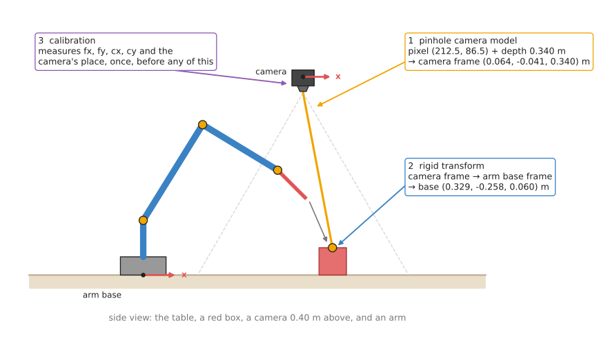
The orange line is the direction that pixel (212.5, 86.5) looks along. The depth reading says the surface is 0.340 m ahead, which gives the point in the camera's frame. A rigid transform then moves it into the arm base's frame, where it becomes (0.329, -0.258, 0.060) m, and calibration measured the numbers that both of those steps use.
Two more techniques answer the questions that come next. When there is no depth reading, pose from points finds a whole object's position and rotation from the pixels of points whose places on the object are known. And multi-view geometry finds depth from two pictures taken from two known places, or from one picture and the fact that the point lies on the table.
This is the same scene that Book 2 uses in cameras: the basics and finding one box. The numbers match those pages, so you can check each step against them.
3. The five techniques#
Section 2 named the five techniques in passing, so this section says what each one covers. Each technique has its own page, and the pages sit in two groups.
The most used group holds the four techniques that nearly every arm with a camera needs. The first three come in the order the steps happen in a running program, except that calibration comes third. This is because calibration happens first on a real robot, but only makes sense once you know what it is measuring. Pose from points comes fourth, because it builds on all three, and calibration already uses it on every picture of the board.
- The pinhole camera model is the rule for how a camera turns a point in the world into a pixel, and how to turn a pixel and a depth back into a point. It covers the four lens numbers, how many millimetres one pixel covers, and how to find a point with no depth reading when you know the table it stands on.
- Rigid transforms are the rule for moving a point from one frame to another. They cover rotation matrices, the 4 × 4 matrix that holds a turn and a shift together, joining frames in a chain, undoing a transform, and quaternions, the four numbers most robot software uses for a rotation.
- Calibration is the method for measuring the numbers the other two need. It covers intrinsic calibration with a printed checkerboard, which finds the lens numbers, and hand-eye calibration, which finds where the camera sits relative to the arm.
- Pose from points, also called Perspective-n-Point (PnP), finds an object's full pose, its position and its rotation, from the pixels of points whose places on the object are known. It covers the reprojection error, PnP inside RANSAC for wrong matches, and why a small printed marker seen face-on gives a poor rotation.
The also used group holds one technique that many arms use, but not all. Most table-top arms get depth from a depth camera, so they do not need to work it out from two pictures themselves. However, arms with a wrist camera, a stereo pair, or no depth sensor at all use it often.
- Multi-view geometry finds depth from two pictures. It covers triangulation, epipolar lines and the essential matrix, rectified stereo and disparity, height from how far a point shifts when the camera slides, and depth from one camera when the point is known to lie on the table.
4. How they compare#
Section 3 described the five techniques one at a time, so this section puts them side by side. The first three do different jobs, so they are not alternatives to each other, and a working arm with a camera uses all three. The last two are two ways of getting 3D information when a depth reading is missing or not good enough. The table below shows, for each technique, what goes in, what comes out, when it runs, and the most common way it goes wrong, so read each row as one technique.
| Technique | What goes in | What comes out | When it runs | The usual mistake |
|---|---|---|---|---|
| Pinhole camera model | a pixel, a depth, and four lens numbers | a point in the camera's frame, in metres | for every pixel you use, on every picture | using fx from a different resolution than the picture |
| Rigid transforms | a point, and a turn and shift for each frame on the way | the same point in another frame | every time a number crosses from one frame to another | joining two transforms in the wrong order |
| Calibration | pictures of a known pattern, and the arm's joint readings | the lens numbers, and the camera's place on the arm | once at set-up, and again after anything is bumped | trusting a low error number from poor pictures |
| Pose from points | known points on an object, their pixels, and the lens numbers | the object's position and rotation in the camera's frame | on every picture where the object is found | trusting the rotation of a small marker seen face-on |
| Multi-view geometry | the same point's pixels in two pictures, and the two camera poses | the point in 3D, or a depth for every pixel | whenever two pictures of the scene are taken | a baseline too short for the distance |
The first two are short formulas that run in microseconds, while pose from points is a small search over six numbers that runs in well under a millisecond. Calibration is a larger optimisation that runs for seconds, and it runs only once. However, calibration decides how accurate all the others can be, as the next section shows.
5. Why small mistakes here matter so much#
Section 4 ended by saying that calibration limits how accurate everything else can be, and this section shows by how much. The formulas in this chapter are exact, but the numbers you feed them are not. Every error in a lens number or a camera pose becomes an error in where the arm goes, and most of these errors grow with distance.
The chart below shows four small mistakes, each on its own, and how far off each
one puts a point, as the object gets further from the camera. The numbers use
the Book 2 camera, with fx = 277.1 pixels.
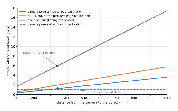
The blue line is a one-pixel mistake in finding the object, and it costs 1.227
mm at 340 mm, because one pixel covers depth / fx there. The purple line is a
camera pose that is turned 1° away from the truth, and it costs 5.935 mm at the
same distance, which is nearly five times as much. So that larger cost is a
calibration error, not a vision error.
The lesson is the same one Book 2 draws in where the millimetres go: a better object detector cannot fix a camera whose position was measured badly. Calibration is usually the largest error in a robot cell, and it is the one nobody sees, because the program still produces sensible-looking numbers.
6. How this chapter connects to the others#
The other six chapters of this book all use points, frames and transforms, which is why this chapter comes first after the introduction.
- Searching and matching works on the 3D points the pinhole model makes. Nearest-neighbour search and iterative closest point (ICP) both need points in one shared frame, and ICP's answer is itself a rigid transform. Its page on image features then finds the matched points that pose from points and multi-view geometry need.
- Fitting and estimation fits planes and shapes to those points, and its RANSAC page is how pose from points and the essential matrix cope with wrong matches. Calibration is itself a fitting problem, because it finds the lens numbers that best explain the pictures, by least squares.
- Image and point cloud processing decides which pixels belong to an object. The pinhole model then turns just those pixels into points.
- Planning and search needs the goal pose in the arm's base frame, and numerical inverse kinematics chains the same rigid transforms that this chapter explains.
- Control and motion moves the arm between poses, and blending two orientations smoothly uses the quaternion blend from the rigid transforms page.
- Decisions and task logic chooses where the camera should look next, which needs the camera's pose for each candidate view.
Book 6 has learned models that do parts of this job differently. Depth from pictures guesses a depth for every pixel from a colour picture alone, or from a stereo pair, which replaces the depth sensor but not the pinhole model, because the guessed depth still goes through the same formula. So multi-view geometry is the measured alternative to that guess. Keypoints and object pose estimates an object's full pose, a rotation and a shift, which is a rigid transform in the camera's frame. Most of those models find keypoints and then hand them to pose from points for the last step. Both kinds of model still need the lens numbers and the camera's pose that calibration measures, so no learned model removes the need for this chapter.
7. Where to read next#
- Start with the pinhole camera model.
- After calibration, read pose from points, then multi-view geometry.
- The map of techniques shows where this chapter sits among all seven.
- The building blocks introduces frames and transforms as one of the common ingredients.
- Book 1's position, frames and transforms builds transforms by hand on a flat two-joint arm, and is the gentlest start.
- Book 3's frames, conventions, and the bug class that comes from mixing them lists the conventions that differ between libraries, and the bugs they cause.
8. Using it in Python#
Section 2 walked the three steps that turn pixel (212.5, 86.5) into a point in the arm's base frame, and section 5 showed how much a small error in any of them costs. This section writes those steps as the Python a ROS 2 node really contains, so that you can see how short the chain is once the libraries are doing the arithmetic. After reading it you should be able to place the boundary between what ROS gives you and what you have to get right yourself.
Two libraries do the work, and they are different in kind. image_geometry holds
the camera's own numbers and does the pinhole arithmetic, while tf2_ros keeps
the tree of frames that the whole robot publishes and hands you the transform
between any two of them at any moment.
import numpy as np
import rclpy
from geometry_msgs.msg import PointStamped
from image_geometry import PinholeCameraModel
from tf2_geometry_msgs import do_transform_point

camera = PinholeCameraModel()
camera.from_camera_info(camera_info_msg)   # the lens numbers, from the camera itself

# Step 1, the pinhole model: the pixel gives a direction, the depth gives the length.
ray = np.array(camera.project_pixel_to_3d_ray((212.5, 86.5)))   # unit length, z ahead
depth = 0.340                                                   # metres, straight ahead
point_camera = ray * (depth / ray[2])        # -> [0.06442 -0.04110  0.340]

# Step 2, a rigid transform: carry that point into the arm's base frame.
stamped = PointStamped()
stamped.header.frame_id = "camera_optical_frame"
stamped.point.x, stamped.point.y, stamped.point.z = point_camera

transform = buffer.lookup_transform("base_link", stamped.header.frame_id,
                                    rclpy.time.Time())   # buffer is a tf2_ros.Buffer
point_base = do_transform_point(stamped, transform)
The libraries give you three things. from_camera_info reads the four lens numbers
and the distortion straight out of the message the camera driver publishes, so the
numbers can never drift apart from the pictures. project_pixel_to_3d_ray undoes
the lens bending and returns a direction of length one, which is why the code
divides by ray[2] before multiplying by the depth: the depth is the distance
straight ahead, not the distance along the slanted ray. Then lookup_transform
finds the whole chain from the camera to the base, joins every link in it, and
does that for the moment you asked about rather than for now.
What you still write yourself is the part between them. You have to fetch the
depth for that pixel out of the depth picture, which means knowing whether the
depth stream is lined up with the colour stream, and you have to skip the pixels
where the depth is 0 because the camera got no reading. You also have to wrap
lookup_transform in a try block, since it raises an exception when the frame
you asked for is not in the tree yet, which happens for the first second after
every start-up.
What you have to decide or measure is which frame the camera's own numbers belong
to, and this is the mistake section 5 is about. image_geometry works in the
optical frame, with z straight out of the lens and y downwards, while the robot
model's camera_link frame has x forwards and z upwards. Passing the wrong one of
the two frame names to lookup_transform gives an answer that looks sensible and
is rotated by 90 degrees, so it is worth testing once with a point you have
measured with a ruler. Book 3's
frames, conventions, and the bug class that comes from mixing them
lists the rest of these conventions. One more practical note: ROS 2 Jazzy renamed
these methods to the underscore spellings used above and left the older
fromCameraInfo and projectPixelTo3dRay in place as deprecated aliases, so
older code you read will use those instead.