This page explains calibration as a technique you can use in any program, and it covers the two calibrations that every arm with a camera needs. Intrinsic calibration measures the camera's lens numbers from pictures of a printed checkerboard, while hand-eye calibration measures where the camera sits relative to the arm. The page then answers four questions about both of them. What exactly is being measured? How does the method find it? How many pictures are enough, and which ones? And how do you know the answer is right?
It is for a reader who has read the two pages before this one: the pinhole camera model, which uses the lens numbers, and rigid transforms, which uses the camera's pose. Book 2 explains why calibration matters so much in calibration, which decides all of it, while this page explains how it works inside.
Contents#
- The idea in one sentence
- Intrinsic calibration: the lens numbers · What is measured · The known pattern · Reprojection error: the number the method makes small · How the numbers are found · A worked run: the lens numbers · The trap: flat-on pictures
- Hand-eye calibration: where the camera is on the arm · Two set-ups · A X = X B, in plain words · A worked run: the camera on the flange
- Checking the result
- Pseudocode
- Where it is used on a robot arm
- Where it works, and where it does not
- Libraries that provide it
- Why calibrate, and what it costs
- The learned alternative
- Where to read next
- Using it in Python
1. The idea in one sentence#
Photograph something whose shape you know exactly, then choose the unknown numbers so that the model predicts the pictures you really took.
Here is an everyday example. To check a kitchen scale, you put a bag of sugar on it that you know weighs exactly 1 kg, so if the scale reads 1.03 kg you now know how far off it is. Calibration does the same with a camera, where the "bag of sugar" is a printed board whose corners are at known places, and the "reading" is where those corners land in the picture.
Both calibrations on this page follow that idea, and they differ only in what is known and what is unknown. Intrinsic calibration knows the board and finds the lens, while hand-eye calibration knows the lens and the arm's movements, and finds the fixed transform between the arm's flange and the camera.
2. Intrinsic calibration: the lens numbers#
What is measured#
Section 1 said that calibration photographs something known, and the first of
the two calibrations photographs a board to learn about the camera. Intrinsic
calibration finds the numbers that belong to the camera itself and do not change
when the camera moves. They are the four lens numbers from the
pinhole camera model, fx, fy, cx and cy,
plus the lens's distortion, which is how much it bends straight lines.
The usual distortion model has five numbers, and they fall into two kinds. Three
of them, k1, k2 and k3, describe radial distortion, which moves each
point towards or away from the middle of the picture by an amount that grows
with the distance from the middle. The other two, p1 and p2, describe
tangential distortion, which comes from a lens that is slightly tilted
relative to the sensor, and which is usually tiny. Book 2 shows the five numbers
arriving in ROS's CameraInfo message, as the field d, in
the ROS camera page.
The picture below shows radial distortion with k1 = -0.12 and k2 = 0.03, on
a camera with Book 2's lens numbers. These values are made up for the example,
but they are typical of a small wide lens.
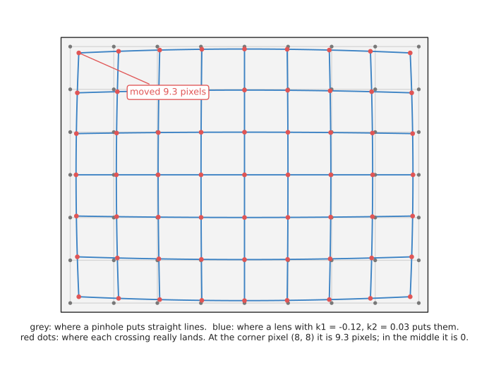
The grey grid is where a perfect pinhole would put the points, and the blue grid is where this lens puts them. In the middle of the picture nothing moves, but near the corner pixel (8, 8) the point moves 9.3 pixels towards the middle, which at 0.34 m is about 11 mm. So a program that ignored this would be accurate in the middle of the picture and badly wrong at the edges.
The known pattern#
The known object is usually a printed checkerboard, whose inner corners,
where four squares meet, lie on a perfect grid. So if the squares are 20 mm, the
corners are at (0, 0, 0), (20, 0, 0), (40, 0, 0) and so on, in millimetres, in
the board's own frame. The board is flat, which means every corner has z = 0.
Then the program finds the corners in each picture to a fraction of a pixel.
OpenCV's findChessboardCorners finds them, and cornerSubPix refines each one
by looking at the brightness pattern around it. A good detector places a corner
to about 0.1 to 0.3 pixels.
So you take many pictures, with the board in a different place and at a different tilt each time. The picture below shows six such views of a board with 9 × 6 inner corners, as the camera sees them.
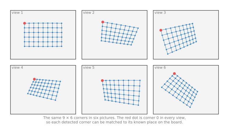
Every picture shows the same 54 corners, and the program knows which corner is which, because the board's pattern tells it where corner 0 is and which way the rows run. That matching of "this pixel is that corner" is what the method feeds on.
A newer kind of board, the ChArUco board, puts a small printed code in the white squares. Each code names its own corners, so the board still works when part of it is hidden or out of the picture, which is why Book 2 recommends it.
Reprojection error: the number the method makes small#
Suppose you guess all the unknown numbers: the lens numbers, the distortion, and the board's pose in each picture. With those guesses, you can work out where every corner should land, using the pinhole model and the distortion formula, and that step is called reprojection.
The reprojection error of one corner is the distance, in pixels, between where it should land and where the detector found it. The method combines all of them into one number, the root mean square (RMS) error: square each distance, take the mean, and take the square root. A good intrinsic calibration has an RMS below one pixel, and a very good one is 0.1 to 0.3 pixels.
So calibration is the search for the guesses that make the RMS as small as possible. That makes it a least-squares problem, the same kind of problem as least-squares fitting a line to points, only with many more unknowns.
How the numbers are found#
The formulas are not linear, because of the division by depth and the distortion terms, so the method cannot solve them in one step. Instead it works in two stages, and the whole method is known as Zhang's method, after the paper that described it in 2000.
- A first guess, ignoring distortion. For a flat board, the mapping from board points to pixels in one picture is a simple formula called a homography: a 3 × 3 matrix that maps one flat plane to another. The program fits one homography per picture from its corners. Each homography constrains the lens numbers a little. With three or more pictures at different tilts, the lens numbers can be solved directly, and each picture's board pose follows.
- Refining everything together. Starting from that guess, the program adjusts all the unknowns at once to shrink the RMS. It uses the Levenberg–Marquardt method: a repeated step that asks "which small change to all the numbers reduces the error most?", makes that change, and repeats until the error stops falling, and this stage also adds the distortion numbers.
With 15 pictures, there are 4 lens numbers, 5 distortion numbers and 6 pose numbers per picture: 99 unknowns. The pictures give 15 × 54 corners, each with two coordinates, which is 1,620 measurements. So having many more measurements than unknowns is what lets the noise average out.
A worked run: the lens numbers#
For this page, we ran OpenCV's calibrateCamera on a simulated camera, so that
the true answer is known. The camera had Book 2's lens numbers and the
distortion from the picture above. Then we placed a 9 × 6 board with 20 mm
squares at 15 random poses, 0.30 to 0.45 m away and tilted up to 35°. After
that, we projected the corners and added random noise of 0.2 pixels to each,
which is what a good corner detector achieves. The table below compares the
answer with the truth, so read each row as one number.
| Number | True value | Calibration found |
|---|---|---|
fx | 277.1 | 276.99 |
fy | 277.1 | 276.70 |
cx | 160.0 | 160.01 |
cy | 120.0 | 118.70 |
k1 | -0.12 | -0.100 |
k2 | 0.03 | -0.139 |
| RMS reprojection error | 0.269 pixels |
The four lens numbers are close, and cy is off by 1.3 pixels, which is the
largest error among them. The RMS of 0.269 pixels is about what the 0.2 pixels
of noise predicts, so the model fits the pictures well.
k2 looks badly wrong, because it is 0.03 in truth and came back as -0.139.
That is not a bug, because k2 controls the bending far from the middle, and in
these 15 pictures no corner came further than 110 pixels from the middle. So the
pictures never tested the corners of the picture, and many different k2 values
fit them equally well. Inside the area the board covered, the found lens and the
true lens send each pixel along almost the same ray, within 1.6 pixels. However,
in the picture's far corners, which the board never reached, they differ by 21
pixels. A calibration is only good where the board has been. So move the
board into every corner of the picture.
The number of pictures also matters, so we measured that too. We repeated the
run 30 times for each count of pictures, and took the middle result. The table
below shows how far fx landed from the truth.
| Pictures | Typical fx error (median of 30 runs) | Worst tenth of runs |
|---|---|---|
| 3 | 2.36 pixels | 4.70 or more |
| 5 | 1.09 pixels | 3.38 or more |
| 8 | 0.83 pixels | 2.17 or more |
| 12 | 0.82 pixels | 2.03 or more |
| 20 | 0.56 pixels | 1.19 or more |
| 30 | 0.58 pixels | 1.06 or more |
The error falls quickly up to about 8 pictures and slowly after 20. So 15 to 25 well spread pictures is a sensible target, because more pictures of the same kind add little.
The trap: flat-on pictures#
We also ran the same calibration on 15 pictures where the board always faced the
camera squarely, with no tilt. The RMS came out at 0.272 pixels, which is as
good as before. However, fx came out as 1,754 instead of 277.1, which is more
than six times too large.
The picture below shows why that happens. A board 0.30 m from a camera with fx
= 277.1, and the same board 1.90 m from a camera with fx = 1,754, give exactly
the same picture when the board faces the camera. So the camera cannot tell
"near and wide" from "far and zoomed in".
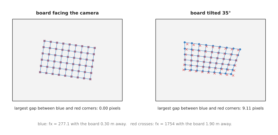
On the left, the blue and red corners sit exactly on top of each other, because the largest gap is 0.00 pixels. On the right, the board is tilted 35°, so the near edge of the board is now closer than the far edge, and the amount of perspective depends on the distance. The two answers then differ by up to 9.11 pixels, so the method can tell which one is right.
The lesson is that a low RMS does not prove a calibration is right, because it proves only that the numbers explain the pictures you took. So tilt the board in every picture, in different directions.
3. Hand-eye calibration: where the camera is on the arm#
Two set-ups#
Section 2 measured the camera on its own, and this section measures where that camera sits on the robot. Hand-eye calibration finds a rigid transform between the arm and the camera, and there are two common set-ups, which find different transforms.
- Eye in hand. The camera is fixed to the arm's wrist. The unknown is
T_flange_camera, the camera's pose relative to the flange, and a board lies still on the table. - Eye to hand. The camera is fixed in the room, looking at the arm. The unknown
is
T_base_camera, the camera's pose relative to the arm's base, while a board is fixed to the gripper.
The two use the same equation and the same solvers, so this page describes only eye in hand, because it is the harder one to picture.
So why not just measure the transform with a ruler? Because the numbers that matter are the camera's optical centre and the direction of its optical axis, and both sit somewhere inside the camera body, where no ruler can reach. And a small error costs a lot: Book 2's error budget shows that 1° of error in this transform costs 5.9 mm at 340 mm.
A X = X B, in plain words#
The arm moves the camera to several poses, and at each one two things are recorded.
- The flange's pose in the base frame. The arm's controller reports it, from the joint angles and forward kinematics.
- The board's pose in the camera's frame. The program finds it from the board's
corners and the lens numbers found by intrinsic calibration. Finding an object's
pose from known points and their pixels is called perspective-n-point (PnP),
and OpenCV's
solvePnPdoes it.
Then take any two of those poses, 1 and 2. Write A for how the flange moved
from pose 1 to pose 2, measured in the flange's own frame at pose 1. Write B
for how the camera moved between the same two poses, measured in the camera's
own frame. A comes from the arm's readings, while B comes from the board,
because the board did not move, so any change in how the camera sees it is the
camera's own movement.
The camera is bolted to the flange, so the two movements are linked by the
unknown bolt, X = T_flange_camera. Going "flange at pose 1, then move A,
then bolt X" must reach the same place as "flange at pose 1, then bolt X, then
move B". Written as transforms:
A · X = X · B
The picture below shows the two poses, drawn from the side.
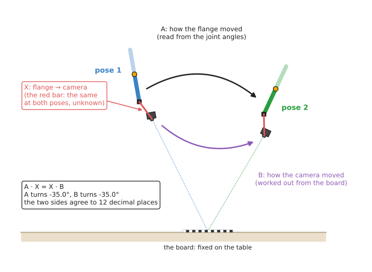
The red bar is X, which is the same at both poses, while the black arrow is
A, known from the joint angles, and the purple arrow is B, found from the
board. In this drawing both movements turn by -35.0°, and the two sides of the
equation agree to 12 decimal places, because the numbers were computed from a
true X.
That also gives a useful check on real data. A and B must always turn by the
same angle, because they are the same physical movement seen from two points on
one rigid body. If a pair of poses shows A turning 14.4° and B turning
12.1°, one of the two measurements is wrong: a blurred picture, or an arm pose
recorded at the wrong moment.
One pair of poses is not enough to find X, because each pair constrains X
only partly. With three or more poses, and movements that turn about at least
two different axes, X is fixed. Movements that only slide, with no turn, tell
the method nothing about X's rotation, so the poses must tilt the camera in
different directions, not just move it around.
So several published methods solve A X = X B from many pairs. Tsai and Lenz's
method (1989) and Park and Martin's method (1994) find the rotation first and
then the shift. However, Horaud and Dornaika's method and Daniilidis's method
(1999) find both together. Andreff's method treats the problem as one set of
linear equations, and OpenCV's calibrateHandEye offers all five.
A worked run: the camera on the flange#
We simulated an eye-in-hand calibration with OpenCV, so that the true X is
known. The true camera sat 60 mm along the flange's x, 20 mm back along its
z, and turned 2° about its y. At each pose, the board's corners were
projected into the camera, given 0.2 pixels of noise, and passed to solvePnP.
Each flange position was given 0.2 mm of noise, which is what a good arm repeats
to. The camera was 0.30 to 0.40 m from the board and tilted up to 25° each way.
The first table shows the five methods, each run 20 times on 15 poses, so read each row as one method and its typical error.
| Method | Shift error (median of 20 runs) | Rotation error (median of 20 runs) |
|---|---|---|
| Tsai | 0.90 mm | 0.128° |
| Park | 0.84 mm | 0.121° |
| Horaud | 0.62 mm | 0.100° |
| Andreff | 17.54 mm | 0.125° |
| Daniilidis | 0.68 mm | 0.109° |
So four methods land under 1 mm and near a tenth of a degree. Andreff's method found the rotation as well as the others, but its shift was 17.5 mm out in this simulation, and we did not investigate why. So the practical lesson is to run two methods on the same data and compare them, and if they disagree by more than a millimetre or two, find out why before trusting either.
Then the second table shows Park's method with different numbers of poses, each run 30 times.
| Poses | Shift error | Rotation error |
|---|---|---|
| 3 | 3.28 mm | 0.50° |
| 5 | 1.51 mm | 0.28° |
| 10 | 1.04 mm | 0.19° |
| 15 | 0.82 mm | 0.13° |
| 25 | 0.72 mm | 0.11° |
As with intrinsic calibration, the error falls fast up to about 10 poses and slowly after. Book 2 reports that careful real calibrations reach about 0.9 mm and a quarter of a degree, which is close to these simulated numbers. However, a real calibration also carries errors this simulation left out, such as an imperfect intrinsic calibration and a board that is not perfectly flat.
4. Checking the result#
Section 3 gave numbers from a simulation where the true answer was known, but on a real robot you never have that. A calibration tool always returns an answer, so checking it is a separate job, and the reprojection error alone is not enough, as the flat-on pictures showed.
- The touch test. Put a small, sharp object on the table. Find it with the camera, move it into the base frame, send the tool tip to it, and measure the miss with a ruler. This tests the whole chain at once: lens numbers, the hand-eye transform, arm kinematics and the tool transform. Book 3 describes it as the known object in a known place.
- The straight edge. Photograph a straight edge near the corner of the picture, undistort it, and check that it comes out straight.
- Two methods, one data set. Run two hand-eye methods and compare.
- Held-out pictures. Keep a few pictures out of the calibration, and then compute their reprojection error with the result, which should be about as small as the RMS of the pictures that were used.
- Several views of one point. With a wrist camera, look at one fixed point from several arm poses. After moving each measurement into the base frame, all of them should land on the same spot. A spread of several millimetres points at the hand-eye transform.
5. Pseudocode#
Sections 2 and 3 described both calibrations, and here is the whole technique in plain steps. The inner solvers are what the libraries provide, so they are named rather than written out.
# Intrinsic calibration
board_corners = the known corner positions in the board frame (z = 0)
views = empty list
for each picture:                          # aim for 15 to 25, tilted, covering the corners
    found, pixels = find_board_corners(picture)
    if not found: skip this picture
    pixels = refine_to_subpixel(picture, pixels)
    add (board_corners, pixels) to views

guess K and one board pose per view from homographies    # Zhang's first stage
refine K, distortion, all board poses to minimise
    sum over views and corners of |project(corner, pose, K, distortion) - pixel|²
report the RMS error, and check it with held-out pictures

# Hand-eye calibration, eye in hand
flange_poses = empty list; board_poses = empty list
for each arm pose:                         # at least 10, tilting about different axes
    move the arm there and wait until it is still
    record T_base_flange from the arm controller
    take a picture; find the board corners
    T_camera_board = solve_pnp(board_corners, pixels, K, distortion)
    add them to the two lists

for each pair (i, j):                      # a sanity check before solving
    A = inverse(T_base_flange[i]) * T_base_flange[j]
    B = T_camera_board[i] * inverse(T_camera_board[j])
    if turn_angle(A) and turn_angle(B) differ by more than 0.5 degrees:
        flag the pair

X = solve_AX_equals_XB(flange_poses, board_poses)   # for example Park's method
check X with a second method and with the touch test
6. Where it is used on a robot arm#
Calibration runs rarely, but everything the camera measures depends on it, and here are the concrete places where it is needed.
- Setting up a new camera. Intrinsic calibration runs once per camera, per resolution. Many depth cameras ship with their own factory calibration, which is usually good enough for the depth camera itself, while a plain colour camera almost never does.
- Mounting a camera on the wrist. Hand-eye calibration runs once after the camera is bolted on, and again after anything touches the mount. Book 2's wrist camera page shows this transform in the middle of every measurement.
- Fixing a camera above the table. Eye-to-hand calibration finds the camera's pose relative to the base. Without it, the fixed camera's points cannot be sent to the arm.
- Adding a second camera. Two cameras looking at the same scene each need their own calibration, and their points only line up if both are right.
- Correcting the arm itself. The same least-squares idea can measure the arm's own small errors, such as a link that is 0.3 mm longer than its drawing. This is called kinematic calibration, and it uses a camera or a tracker to watch the flange at many poses.
- Undistorting every picture. After intrinsic calibration, every picture, or every pixel the program uses, is corrected before the pinhole camera model is applied.
7. Where it works, and where it does not#
The uses in section 6 all assume the calibration itself was good, and that depends on the data you gave it. Calibration works well when the pictures and poses give it enough to go on, so most failures come from poor data rather than poor solvers. The table below lists the common ones, so read each row as what goes wrong, what you see, and what to do.
| What goes wrong | The sign you see | What to do instead |
|---|---|---|
| the board always faces the camera | a low RMS, but fx and the board distance are both far off | tilt the board 20° to 45° in different directions |
| the board never reaches the picture's corners | points near the edges of the picture are several millimetres off; k2 and k3 look strange | fill the whole picture, including every corner, across the set of pictures |
| a blurred or partly hidden board | corners detected in the wrong place; a few pictures with a much larger error than the rest | drop the worst pictures; use a ChArUco board |
| the printed board is not flat, or its squares are not the size you typed | a consistent size error in every measurement | mount the print on glass or aluminium; measure the squares with calipers |
| hand-eye poses that only slide, or turn about one axis | a hand-eye shift error of several millimetres or more | turn the wrist about at least two different axes between poses |
| the arm pose read while the arm was still moving | A and B turn by different angles for some pairs | wait until the arm stops; check the angle pairs |
| the camera was bumped, or its focus or zoom changed | the touch test misses by more than it used to | recalibrate; lock the focus; add a periodic check |
| a different resolution than was calibrated | every point is scaled towards or away from the picture's middle | calibrate at the resolution you use, or scale the numbers exactly |
Calibration also does not fix things that are not in its model. For example, it cannot correct a depth camera's depth errors on shiny objects, and it cannot correct an arm whose links bend under load. And it describes the camera only as it was on the day it was measured.
8. Libraries that provide it#
Because the solvers are long and the details matter, calibration is almost always done with a library. The table below lists well-known tools, so read each row as where to find it, which languages it covers, and what to call.
| Library or tool | Languages | What to call | Note |
|---|---|---|---|
| OpenCV | C++, Python | findChessboardCorners, cornerSubPix, calibrateCamera, solvePnP, calibrateHandEye in the calib3d module | the reference implementation of both; calibrateHandEye offers the Tsai, Park, Horaud, Andreff and Daniilidis methods |
OpenCV aruco module | C++, Python | ChArUco board detection | for boards that may be partly hidden |
ROS camera_calibration | Python | the cameracalibrator node | a window that guides you to move the board, then writes the camera's calibration file |
| easy_handeye2 | Python, ROS 2 | its calibration nodes | the usual ROS 2 tool for hand-eye calibration; it collects the poses and calls OpenCV's solvers |
| MoveIt Calibration | C++, ROS | its RViz plugin | hand-eye calibration inside MoveIt; Book 2 notes its ROS 2 state as partly maintained |
| Kalibr | C++, Python | its command-line tools | for rigs of several cameras, and for cameras with a motion sensor |
| mrcal | C, Python | its command-line tools | reports how uncertain each calibrated number is, not just its value |
| Ceres Solver | C++ | its least-squares problem classes | for writing your own calibration, such as kinematic calibration |
Book 2 lists the licences of these tools in calibration, which decides all of it.
9. Why calibrate, and what it costs#
This section answers the four questions for calibration: what it is, what it does for you, why it rather than the obvious alternative, and what it costs.
It is the method of photographing a known object and choosing the camera's numbers so that the model predicts the pictures. So it gives you the lens numbers, the distortion, and the camera's place on the arm, each with a measured error.
The obvious alternative is to use numbers from somewhere else: the lens numbers
from the camera's datasheet, and the camera's position from the mount's drawing.
That costs nothing and needs no board, and for the lens numbers it is often
close. Book 2 works out the Raspberry Pi camera's fx from its datasheet in
two separate ways,
and they agree within 0.2 per cent. However, a datasheet does not know your
particular lens's distortion or where its sensor really sits, and a drawing does
not know where the optical centre is inside the camera body. On a wrist camera,
an error of 1° from the drawing costs about 6 mm at a normal working distance,
so calibration measures the actual camera on the actual arm.
So the cost is this. You need a flat, accurately printed board, along with 15 to 25 careful pictures and 10 to 20 careful arm poses. You also need to check the result separately, because the tools always return an answer. And you need to do it again whenever the camera is bumped, refocused, or moved to a different resolution.
10. The learned alternative#
No model in Book 6 measures a camera's lens numbers or its place on the arm. So the learned alternative is to skip calibration altogether. A policy, a network from Book 7's movement models, turns pictures straight into arm movements, so no lens numbers or hand-eye transform appear anywhere in the plan. But the policy then learns one camera in one place. Book 7's diffusion and flow policies notes that a camera moved by a few centimetres can confuse it, and the fix is more demonstrations, while a calibrated camera can be moved and recalibrated in half an hour. For the arm's own geometry, Book 7's learned arm models describes a small network that learns what kinematic calibration leaves out, such as links that bend under their own weight. It then adds that on top of the calibrated numbers rather than replacing them.
11. Where to read next#
- The previous pages, the pinhole camera model and rigid transforms, use every number this page measures.
- The overview shows how calibration errors compare with the other errors in a measurement.
- Least-squares fitting explains the kind of problem that calibration solves, on simpler examples.
- RANSAC is how some tools reject bad pictures or bad corners before fitting.
- Book 2 goes deeper into why calibration matters in calibration, which decides all of it and the wrist camera, end to end.
12. Using it in Python#
Sections 2 and 3 described the two calibrations and section 5 gave both as pseudocode, while section 8 named OpenCV as the library that implements them. This section shows the OpenCV calls themselves, because the pseudocode hides how little code the two solvers need once the pictures and the poses have been collected. After reading it you should see that the solver is three lines and the collecting is everything else.
Intrinsic calibration comes first, and it is two calls per picture followed by one call over all of them. The board below has 9 by 6 inner corners and 20 mm squares.
import glob

import cv2
import numpy as np

pattern = (9, 6)
square_m = 0.020

# The board's own corners, in the board's frame: z is 0 because the board is flat.
board_points = np.zeros((pattern[0] * pattern[1], 3), np.float32)
board_points[:, :2] = np.mgrid[0:pattern[0], 0:pattern[1]].T.reshape(-1, 2) * square_m

object_points, image_points = [], []
for path in sorted(glob.glob("board/*.png")):
    grey = cv2.imread(path, cv2.IMREAD_GRAYSCALE)
    found, corners = cv2.findChessboardCorners(grey, pattern)
    if not found:
        continue                       # this picture is unusable, and that is normal
    corners = cv2.cornerSubPix(
        grey, corners, (11, 11), (-1, -1),
        (cv2.TERM_CRITERIA_EPS + cv2.TERM_CRITERIA_MAX_ITER, 30, 0.001))
    object_points.append(board_points)
    image_points.append(corners)

rms, K, dist, rvecs, tvecs = cv2.calibrateCamera(
    object_points, image_points, grey.shape[::-1], None, None)
print(rms, "pixels RMS reprojection error")
Hand-eye calibration then reuses the rvecs and tvecs that came back, because
each of them is already the board's pose in the camera for one picture. What you
add is the arm's own pose for the same picture, read from tf2 at the moment the
picture was taken.
R_target2cam = [cv2.Rodrigues(r)[0] for r in rvecs]   # rotation vector to matrix
t_target2cam = tvecs

R_cam2gripper, t_cam2gripper = cv2.calibrateHandEye(
    R_gripper2base, t_gripper2base,       # the arm's flange pose, one per picture
    R_target2cam, t_target2cam,       # the board's pose in the camera, one per picture
    method=cv2.CALIB_HAND_EYE_TSAI)
What the library does for you is the whole of both solvers. findChessboardCorners
finds the corners and puts them in a known order, cornerSubPix refines each one to
a fraction of a pixel, and calibrateCamera runs the first guess and the
least-squares refinement of section 2 over every picture at once, returning the four
lens numbers, the five distortion numbers and the board's pose in each picture.
calibrateHandEye solves the equation of section 3, and it offers the Tsai, Park,
Horaud, Andreff and Daniilidis methods behind that one method argument.
What you still write yourself is the collecting, and it is the larger half. You write the loop over the pictures, you skip the pictures where the board was not found, and you have to pair each picture with the arm pose at the moment it was taken rather than the pose a moment later, which means either stopping the arm or recording both with timestamps. Nothing checks that the pairing is right, and a single mismatched pair moves the answer by centimetres.
What you have to decide or measure is the board and the poses. You measure the
square size with calipers, on the printed board rather than from the file you sent
to the printer, because printers scale. You decide how many pictures to take and
how varied they are, which section 2 covers, and for hand-eye you decide the
rotations, because calibrateHandEye fails outright when the flange poses are not
turned enough relative to each other. Finally, the RMS reprojection error that
calibrateCamera returns is not a verdict: section 4 shows how a low number can
come from poor pictures, so check the answer against a measured distance instead.